01-02 7 28466 Rev H
NOVUS B-VENT INSTALLATION INSTRUCTIONS
3. FIRESTOP SPACER/VENT
INSTALLATION
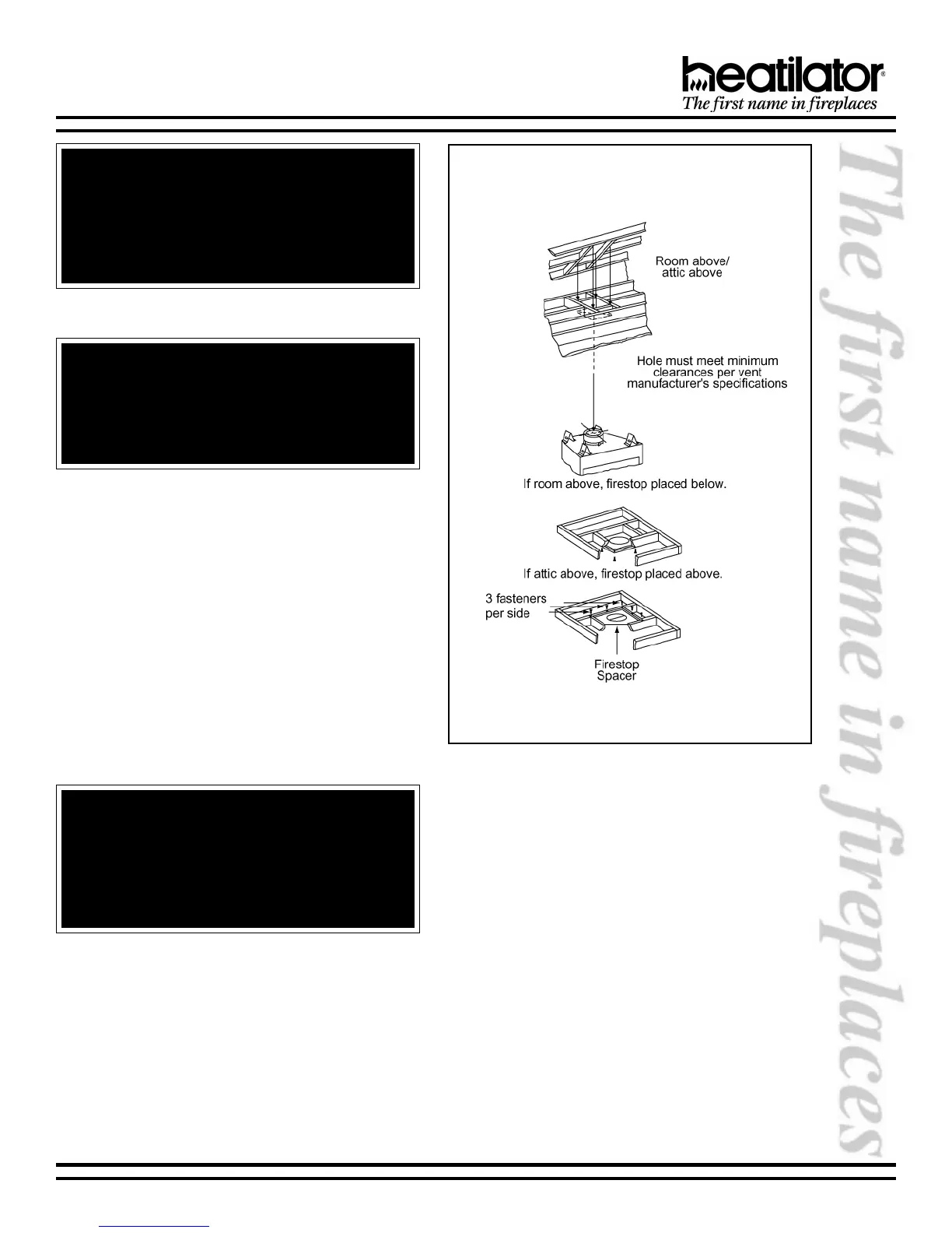
Frame an opening and install a firestop spacer
whenever the vent penetrates a ceiling floor area, as
shown in Figure 6. Frame the opening with the same
sized lumber as used in the ceiling/floor joist. Unless
the flue is offset, the hole should be directly above the
appliance. DO NOT pack insulation around the vent.
Assemble vent sections with three screws per joint.
WARNING - RISK OF FIRE
Always maintain minimum clearances or greater
around the vent system. Do not pack air spaces with
insulation or other material. The flow of combustion
and ventilation air must not be obstructed.
WARNING!
The horizontal run of vent must have a 1/4 rise for
every 1 ft. of run towards the termination. Never allow
the vent to run downward. This could cause high
temperatures and may present a fire hazard.
WARNING!
When vent sections exceeding three feet in length
are installed between an offset/return, structural
support must be provided to reduce off-center
loading and prevent vent sections from separating
at the vent joints. Follow all B-vent manufacturer
guidelines.
4. CHASE/TERMINATION INSTALLATION
Figure 7 and Table 1 specify minimum vent heights
for various pitched roofs. Vent sections may have to
be cut to a certain length.
These vent heights are necessary for safety and do
not ensure draft-free operation. Trees, buildings,
adjoining roof lines, adverse conditions, etc., may
create a need for a taller vent should down drafting
occur.
Figure 6
Installing the Firestop Spacer
 Loading...