28466 Rev H 6 01-02
NOVUS B-VENT INSTALLATION INSTRUCTIONS
CAUTION
Provide adequate clearances around the air openings into the combustion chamber and adequate accessibility
clearances for servicing and proper operation.
D. SETTING THE APPLIANCE
1. POSITIONING THE APPLIANCE
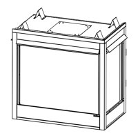
This appliance may be placed on a smooth
combustible or noncombustible, continuous flat
surface. When the appliance is installed directly on
carpeting, tile or other combustible material other than
wood flooring, the appliance shall be installed on a
metal or wood panel extending the full width and depth
of the appliance. Slide the appliance into position and
level from side-to-side and front-to-back. Shim with
noncombustible materials as necessary.
E. VENTING
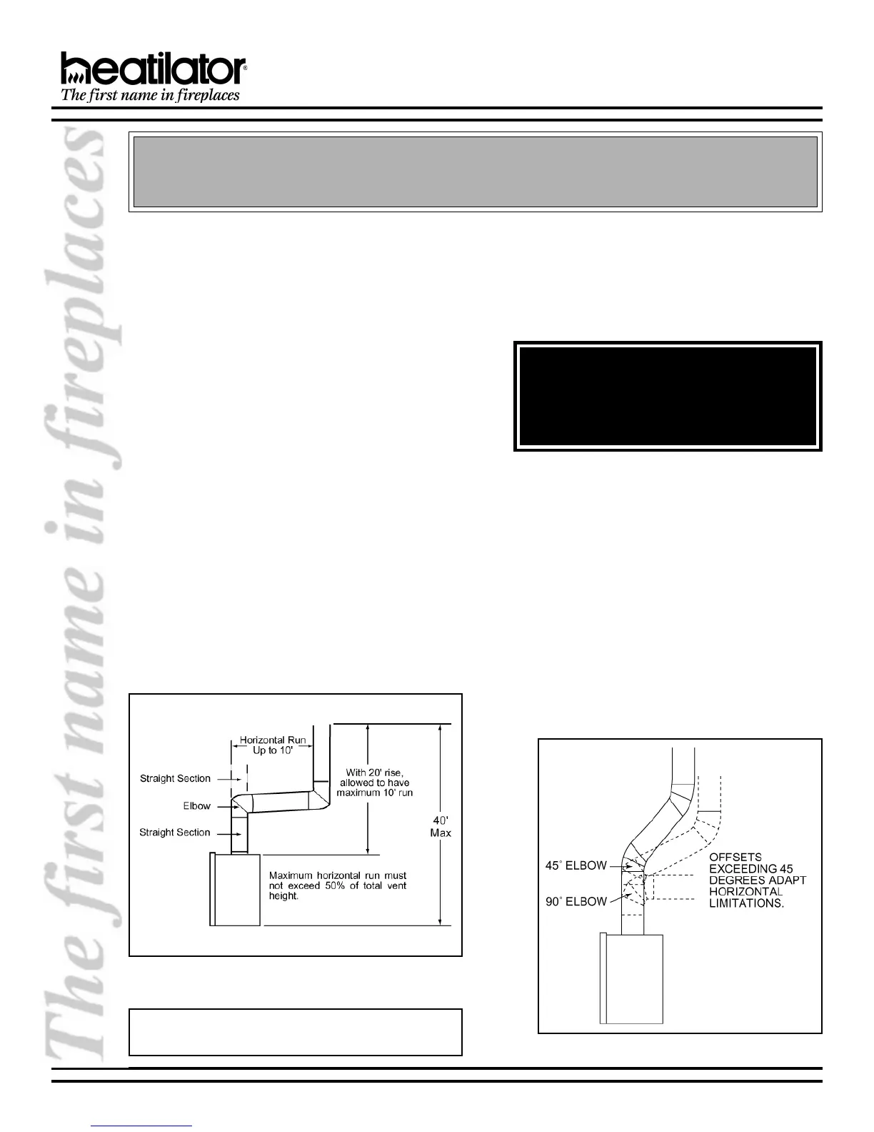
1. VENT HEIGHT
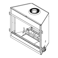
This appliance requires a 5 B-vent for operation.
Never downsize pipe. It must be terminated above
the roof line. Follow all B-vent requirements and
installation instructions, including minimum
clearances.
The minimum height of vent installation must be nine
feet from the top or twelve feet from the base of the
appliance. Horizontal run must never exceed 50% of
the height of the vent system as shown in Figure 4.
Secure the appliance by bending out the nailing
flanges on each side of the appliance and nail to
framing. The nailing flanges have been positioned
5/8 inch back from the front of the appliance to allow
the addition of drywall.
2. ATTACHING VENTING
a. Assembling Vent Sections. Attach straight vent
section to the top of appliance. Use only B-vent
sections.
b. Attaching the Vent to the Collar Shield. Three
tabs extend from the collar shield to the B-vent
section. Screw the tabs to the B-vent section using
self-tapping screws.
c. Using Elbows. Elbows exceeding 45° from the
vertical shall be considered horizontal and
therefore adapt horizontal run limitations. See
Figure 5.
Figure 4
Venting Off the Top of Appliance
Note: Vertical rise off the top of the firebox before elbow-
ing creates a less restrictive venting environment.
Figure 5 - Using Elbows
WARNING!
To prevent contact with sagging or loose
insulation, the appliance must not be installed
against vapor barriers or exposed insulation.
Localized overheating could occur and a fire
 Loading...