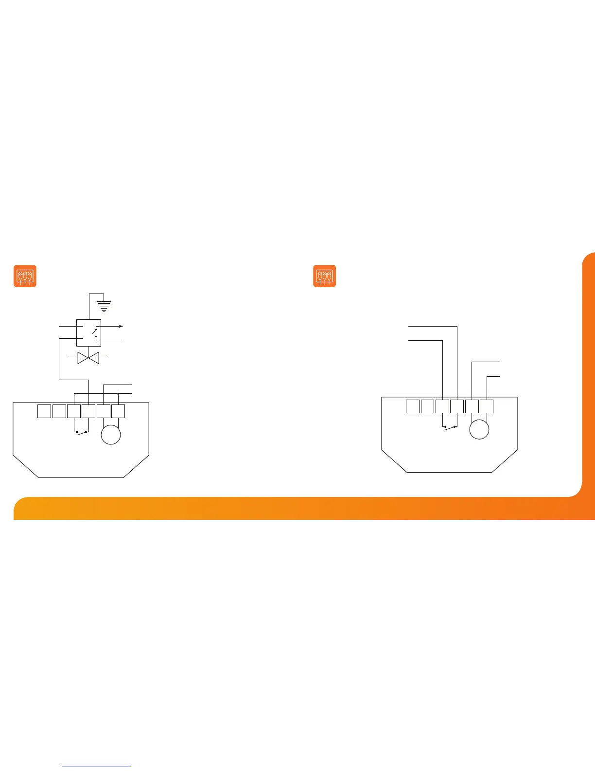
Wiring Diagram - PRT-TS to Valve
P/L = Permanent Live
S/L = Switched Live
Supply In - 85V-230V AC
Max Load - 3 Amps
To connect boiler, consult boiler
manufacturers wiring diagram
For Voltfree connections, wire
the P/L and S/L directly to the
boiler or if there is no system
valve take A1 & A2 directly
to the boiler
Heating Valve
L
P/L
To Boiler S/L
Live
Neutral
N
PRT-TS
NA2A1
230VAC
L
Wiring Diagram - PRT-TS to Boiler Voltfree
Supply In - 85V-230V AC
Max Load - 3 Amps
VOLT FREE TO BOILER
Live
Neutral
PRT-TS
NA2A1
230VAC
L
LS & LR are normally the room
thermostat connections.
For 230V switched live to boiler
on A2 link L to A1
LR
LS