Installation & Commissioning
38
Hectronic GmbH | Allmendstrasse 15 | D-79848 Bonndorf | Tel. +49 7703 9388-0 | Fax +49 7703 9388-60 | mail@hectronic.com
Managing Directors: Stefan Forster, Eckhard Fechtig, Frank Gampp | District Court Freiburg, HRB 621170 | VAT ID No.: DE170986709
3.2.6. Surge Arrester
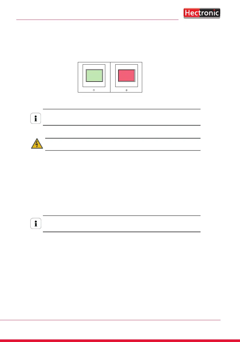
There is also the option of installing a surge arrester in the supply variant with mains connection. A viewing window indicates
whether an overvoltage has occurred:
Normal (green) Overvoltage (red)
Even with defective surge arresters, the mains voltage supply of the parking machine is not interrupted. In the
course of regular maintenance work, the surge arresters should therefore be visually inspected, especially after
thunderstorms. Defective surge arresters no longer have a surge protection function and must be replaced.
The surge arresters may only be replaced if the mains voltage line has been de-energised by an authorised
electrician.
3.2.7. Installation Instructions for External Solar Supply
1. Insulate the two connecting cables (2 x 2.5 mm²) and insert them into the empty conduit and conduit post.
2. Screw the solar module onto the solar bracket.
3. Place solar module with solar bracket completely on tubular post. At the same time, the connecting lines must be pulled
back from the PA supply room. Align the solar bracket with the solar module for optimum solar yield, screw it onto the
tubular post and secure it with the pin.
The full charging capacity is only achieved by best sunlight! If installation facing south is not possible, the
necessary charging of the batteries is not guaranteed. The possible obstruction of sunlight by trees, houses,
narrow street canyons, etc. must also be checked on a case-by-case basis.
4. The connecting lines of the solar module are to be connected to the solar controller according to the plan below.