15
441 01 2121 01
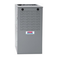
Figure 17 − Typical Attic Installation
30-IN . (762mm)
MIN WORK AREA
6 ″
M IN
*
TYPE-B
VENT
17
3
/
4
″
22
″
SHEET
MET AL
SEDIMENT
TRAP
EQUIPMENT MANU AL
SHUT -OFF GAS VA LV E
LINE CONT A CT ONL Y PERMISSIBLE BETWEEN
LINES FORMED BY INTERSECTIONS OF
THE T OP AND TW O SIDES OF THE FURNA CE
JA CKET AND BUILDING JOISTS ,
STUDS , OR FRAMING.
GAS
ENTR Y
17
3
/
4
″
(451mm)
OVERALL
4
3
/
4
″
(121mm)
UNDER DOOR
1 ″
(25mm)
UNDER FURNACE
EXTEND OUT 12 ″
(305mm)
FR OM FA CE OF DOOR
* WHEN USED W ITH
SINGLE W ALL VEN T
CONNECTIONS
UNION
(152mm)
(451mm)
(559mm)
A10164
Downflow Furnaces
Connect supply−air duct to supply−air outlet on furnace. Bend
flange inward past 90 with wide duct pliers (See Figure 14)
The supply−air duct must be connected to ONLY the furnace
supply outlet or air conditioning coil casing (when used).
When installed on combustible material, supply−air duct must
be connected to ONLY the accessory subbase or a factory
approved air conditioning coil casing. DO NOT cut main
furnace casing to attach supply side air duct, humidifier, or
other accessories. All accessories MUST be connected to
duct external to furnace casing.
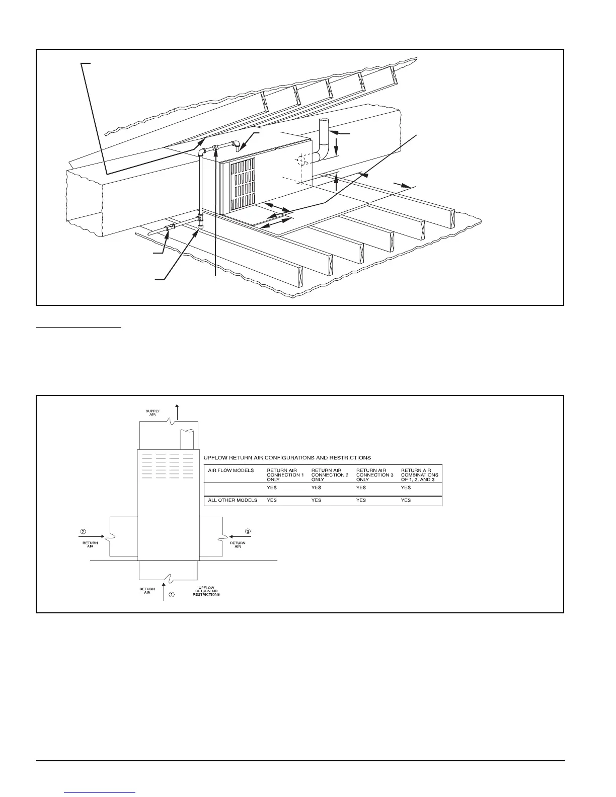
Figure 18 − Upflow Return Air Configurations and Restrictions
5 TONS AND
GREATER
*
*
2000 CFM AND GREATER AT .6 ESP HI COOLING SPEED