31
441 01 2121 01
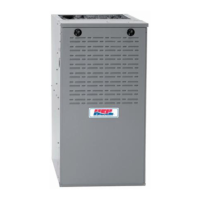
Figure 44 − Horizontal Left Application − Vent Elbow Up
SEE NOTES: 1,2,4,5,7,8,9 on the page
following these figures
A03215
Figure 45 − Horizontal Left Application − Vent Elbow
Right
SEE NOTES: 1,2,4,5,7,8,9 on the page
following these figures
A03216
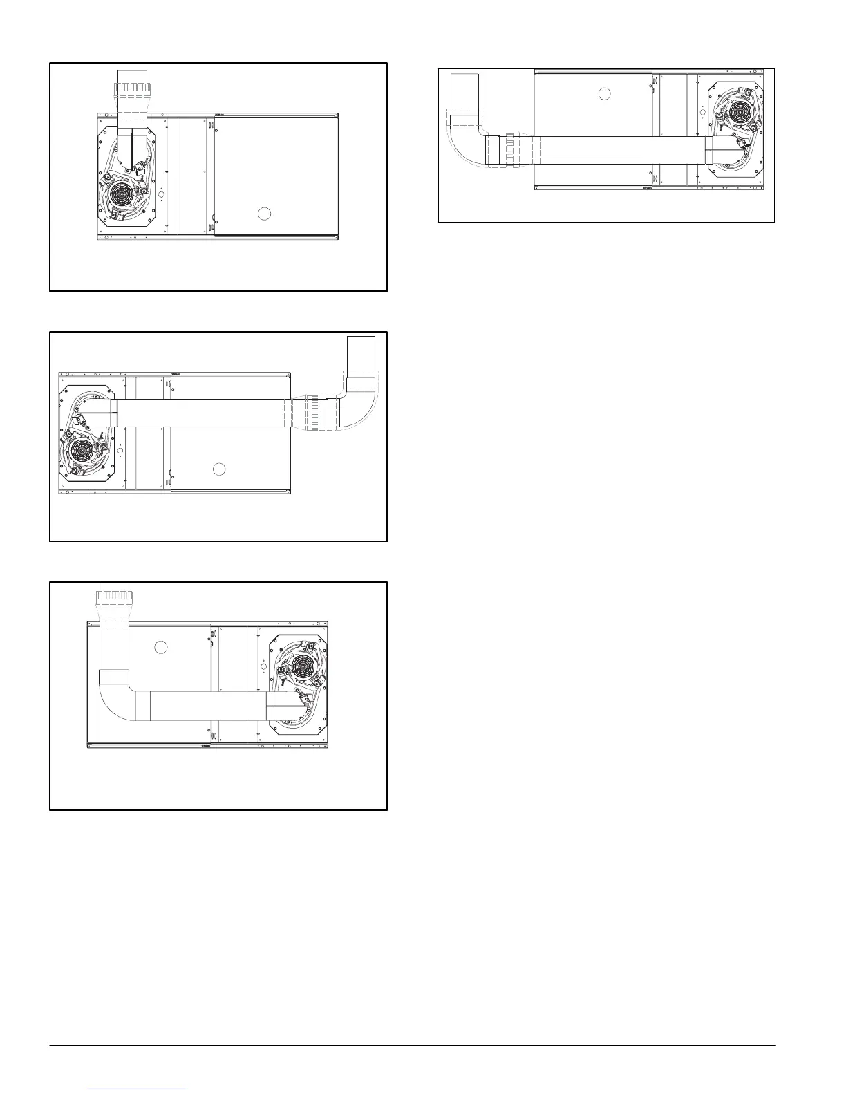
Figure 46 − Horizontal Right Application − Vent Elbow
Left then Up
SEE NOTES: 1,2,4,5,7,8,9 on the page
following these figures
A03219
Figure 47 − Horizontal Right Application−Vent Elbow Left
SEE NOTES: 1,2,4,5,7,8,9
A02068
VENTING NOTES FOR Figure 35 − Figure 47
1. For common vent, vent connector sizing and vent
material: United States−−use the NFGC.
2. Immediately increase to 5−in. (102 mm) or 6−in. (152
mm) vent connector outside furnace casing when 5−in.
(127 mm) vent connector is required, refer to Note 1
above.
3. Side outlet vent for upflow and downflow installations
must use Type B vent immediately after exiting the
furnace, expect when Downflow Vent Guard Kit is used
in the downflow position.
4. Type−B vent where required, refer to Note 1 above.
5. A 4−in.(102 mm) single−wall (26 ga. min.) vent must be
used inside furnace casing and when the
NAHB00301VC Downflow Vent Guard Kit is used
external to the furnace.
6. Accessory Downflow Vent Guard Kit is required in
downflow installations with lower vent configuration.
7. Chimney Adapter Kit may be required for exterior
masonry chimney applications. Refer to Chimney
Adapter Kit for sizing and complete application details.
8. Secure vent connector to furnace elbow with (2)
corrosion−resistant sheet metal screws, spaced
approximately 180 apart.
9. Secure all other single wall vent connector joints with
(3) corrosion resistant screws spaced approximately
120 apart. Secure Type−B vent connectors per vent
connector manufacturer’s recommendations.
NOTE: For the following applications, use the minimum vertical heights as specified below. For all other applications, follow
exclusively the National Fuel Gas Code.
FURNACE
ORIENTATION
VENT ORIENTATION FURNACE INPUT
(BTUH/HR)
MIN. VENT
DIAMETER
IN. (mm)*
MIN. VERTICAL VENT
HEIGHT
FT. (M)**
Downflow Vent elbow left, then up Figure 35 132,000/110,000 (3 ton only) 5 (127) 12 (3.6)
Horizontal Left Vent elbow right, then up Figure 38 132,000 5 (127) 7 (2.1)
Horizontal Left Vent Elbow up Figure 39 132,000 5 (127) 7 (2.1)
Downflow Vent elbow up then left Figure 33 110,000 (3 ton only) 5 (127) 10 (3.0)
Downflow Vent elbow up, then right Figure 36 110,000 (3 ton only) 5 (127) 10 (3.0)
NOTE: All vent configurations must also meet National Fuel Gas Code venting requirements NFGC.
*4−in. (102 mm) inside casing or vent guard
**Including 4 in. (102 mm) vent section(s)