JS07N·JS07·JS08·JS12·JS14
45
Maintenance
Proper brake action is essential to safe ma-
chine operation. The drive brake function
should operate smoothly, free of hesitation,
jerking and unusual noise. Hydraulically-re-
leased individual wheel brakes can appear to
operate normally when not fully operational.
Perform this procedure with the machine on a
firm, level surface that is free of obstructions.
Be sure the platform deck extension deck is
fully retracted and the platform is in the stowed
position.
1. Mark a test line on the ground for refer-
ence.
2. Turn the key switch to platform control
and pull out the red Emergency Stop but-
ton to the on position at both the ground
and platform controls.
3. Lower the platform to the stowed posi-
tion.
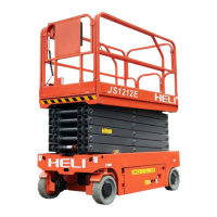
4. Press the drive function select button.
a. Drive function select button
5. Choose a point on the machine; i.e., con-
tact patch of a tire, as a visual reference
for use when crossing the test line.
6. Move the control handle to drive at the
maximum speed, and release handle
while across the ground test line.
7. Measure the distance between the refer-
ence point and the test line.
⊙ Result: The machine should stop within a
specified the braking distance.
¤ Result: The machine do not stop within a
specified the braking distance.
Note: The brakes must be able to hold the
machine on any slope it is able to climb.
8. Replace the brake, repeat the process
from step1.
B-8
Test the Drive Speed-Platform
Stowed
This procedure should be performed every 250
hours or quarterly, whichever comes first.
Proper drive functions are essential to safe
machine operation. The drive function should
respond quickly and smoothly to operator con-
trol. Drive performance should also be free of
hesitation, jerking and unusual noise over the
entire proportionally controlled speed range.
Perform this procedure with the machine on a
firm, level surface that is free of obstructions.
1. Create start and finish lines by marking
two lines on the ground 40 feet/12.2 m apart.
2. Turn the key switch to platform control
and pull out the red Emergency Stop button to
the on position at both the ground and plat-
form controls.
3. Lower the platform to the stowed position.
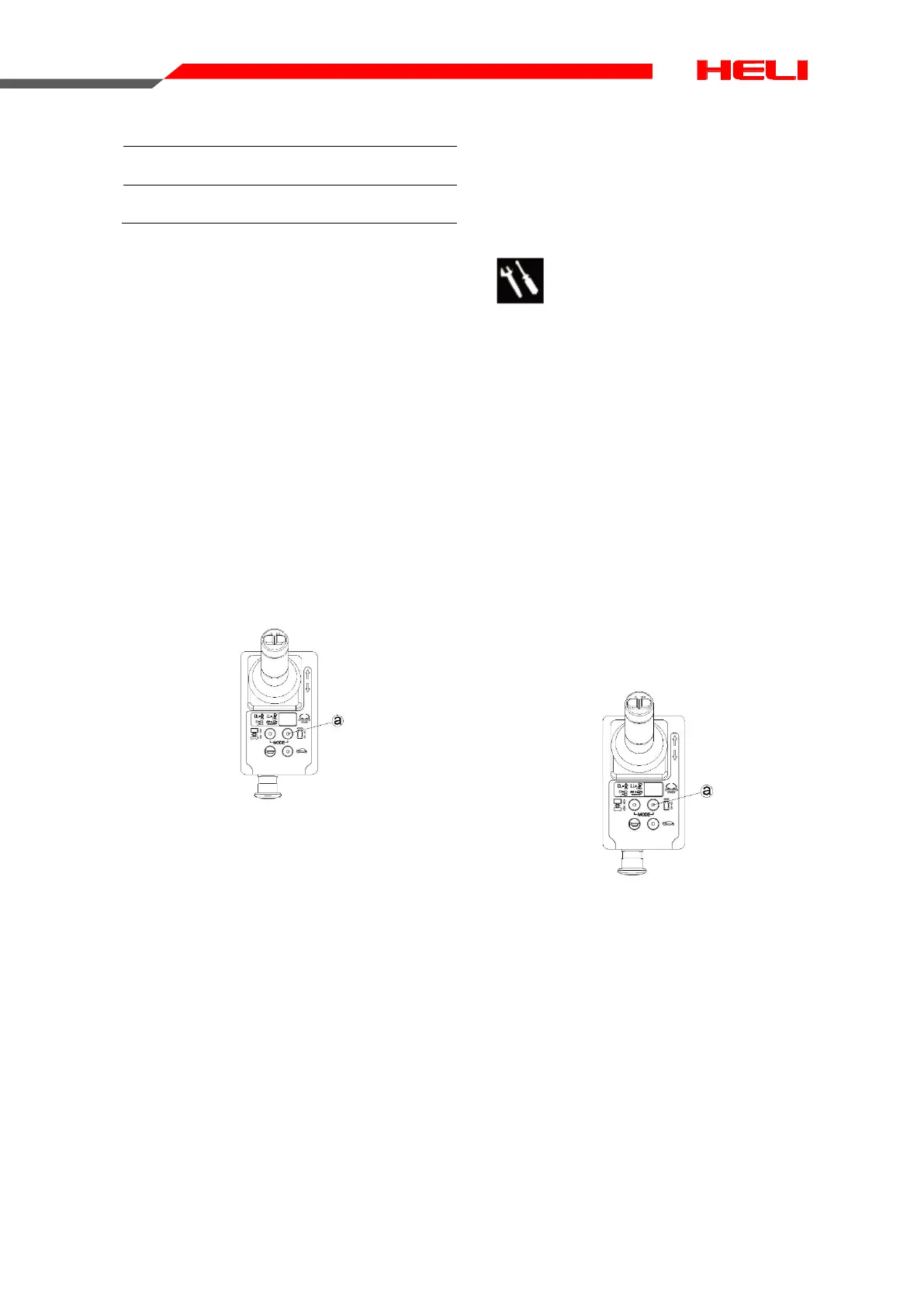
4. Press the drive function select button
a. Drive function select button
5. Choose a point on the machine; i.e., con-
tact patch of a tire, as a visual reference for
use when crossing the test line.
6. Move the control handle to drive at the
maximum speed. Begin timing when the refer-
ence points cross the start line.
7. Continue at full speed and note the time
when your reference point on the machine
passes the finish line. Refer to specification.
Braking distance
Max braking distance 40cm±20cm
 Loading...