16
Initial start-up and functions
1
Optical Input (optional)
Optical inputs in SPDIF format for connecting signal
sources with a digital audio output. The sampling
rate of this input must be between 28 and 96 kHz.
Please note: The digital inputs are not part of the
C FOURs standard equipment. These can only be
retrotted with the optionally available HELIX Digital
Input Module HDM 2.
Important: The signal of a digital audio source nor-
mally does not contain any information about the
volume level. Keep in mind that this will lead to full
level on the outputs of the HELIX C FOUR. This
may cause severe damage to your speakers. We
strongly recommend to only use volume controlled
audio sources!
Note: This amplier can only handle stereo input
signals and no MP3- or Dolby-coded digital audio
stream!
Note: It is possible to use the Optical Inputs and the
lowlevel Line Input at the same time.
2
SPDIF Direct In switch (optional)
Due to the SPDIF Direct In switches, the input stag-
es of the individual channel pairs of the C FOUR
can be bypassed and the input signal of the Optical
Inputs directly and losslessly routed from the inte-
grated DA converter to the internal power stage. To
activate the direct signal routing you have to set the
SPDIF Direct In switch to “On”.
Please note: The SPDIF Direct In function is not
part of the C FOURs standard equipment. It is sole-
ly included in the optionally available HELIX Digital
Input Module HDM 2.
Note: These switches only aect the signal routing
of the respective Optical Input.
Note: The appropriate channel pair of the ampli-
er must be operated in fullrange mode for routing
the digital input signal directly to the power stage.
Therefore change the position of the respective
X-Over switch to “FULLRANGE“ (see page 18,
item 16).
Note: If the switch is set to “On” position the lowlev-
el Line Input (3) as well as the Level controls (10)
are without function!
3
Line Input
4-channel lowlevel line input to connect signal
sourc es such as head units / radios / DSPs.
4
GND
The ground cable should be connected to a common
ground reference point (this is located where the
negative terminal of the battery is grounded to the
metal body of the vehicle) or to a prepared metal lo-
cation on the vehicle chassis i.e. an area which has
been cleaned of all paint residues. Recommended
cross section: min. 16 mm² / AWG 6.
5
+12 V
Connect the +12 V power cable to the positive ter-
minal of the battery. Recommended cross section:
min. 16 mm² / AWG 6.
6
REM
The remote lead should be connected to the remote
output / automatic antenna (aerial positive) output
of the head unit / car radio. This is only activated
if the head unit / car radio is switched on. Thus the
amplier is switched on and o together with the
head unit / car radio.
7
Output channels
Speaker outputs of the channels A - D to connect
speaker systems. The impedance per channel
must not be lower than 2 Ohms (4 Ohms in bridged
mode).
8
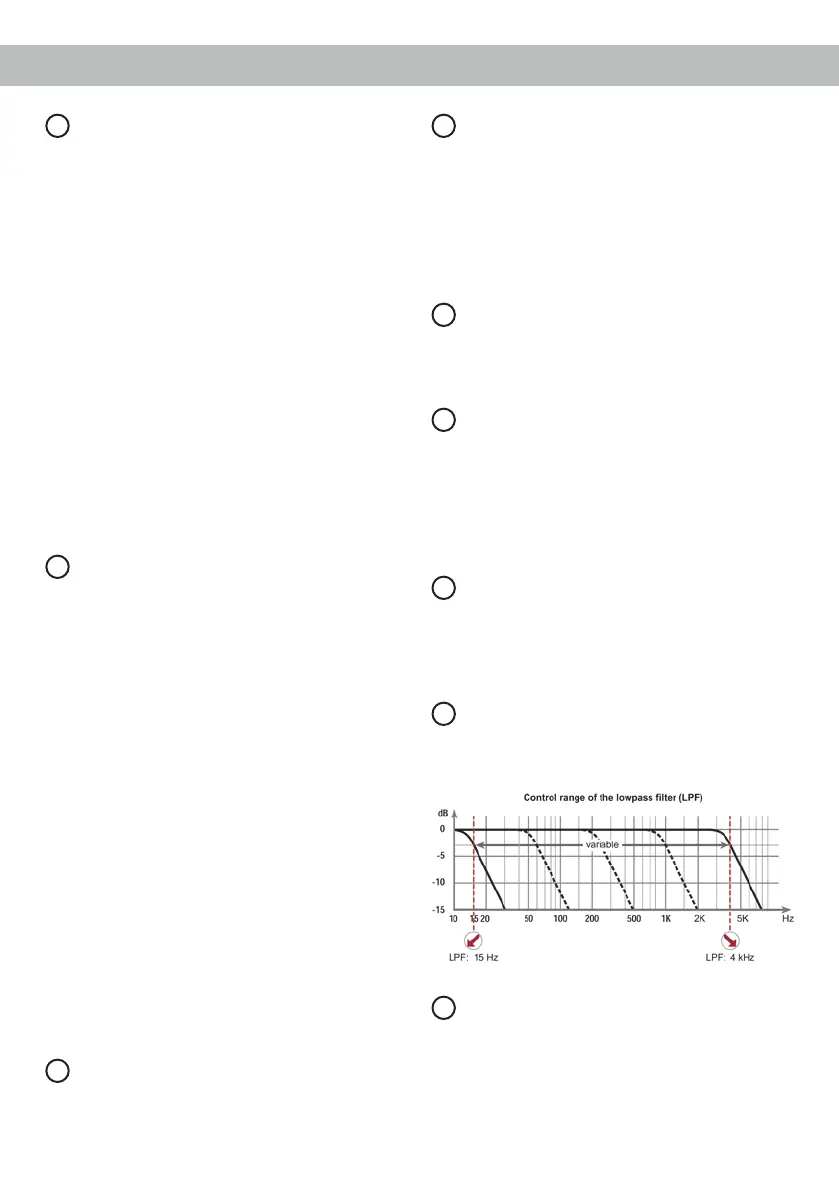
LPF
These controls are used to adjust the crossover
frequency of the lowpass lter of the channel pairs
A / B and C / D from 15 Hz to 4,000 Hz.
9
HPF
These controls are used to adjust the crossover
frequency of the highpass lter of the channel pairs
A / B and C / D from 15 Hz to 4,000 Hz.