14
Initial start-up and functions
320 Hz the highpass should be adjusted to 80 Hz
or less (one octave = doubled frequency or halved
frequency). If a subwoofer is connected we recom-
mend to use the highpass control (control 4) as vari-
able subsonic / low-frequency highpass lter or turn
it counterclockwise to 15 Hz to get a subsonic lter.
6
Input Mode
This switch is used to route the input signals to the
respective amplier channels.
4-channel mode: If the head unit / car radio provides
two stereo outputs (front left / right, rear left / right),
all four signal inputs of the amplier are supplied
with the corresponding output signals of the head
unit / car radio.
2-channel mode: If the head unit / car radio only
provides one stereo output, all amplier channels
are supplied with this signal. This means, that only
the RCA / highlevel inputs of the channels A and B
need to be connected. In this mode the input signal
of channel A is routed to channel C and channel
B is routed to channel D. Please consider that the
fader and balance control of the head unit have the
same effect on channels A and C and respectively
B and D.
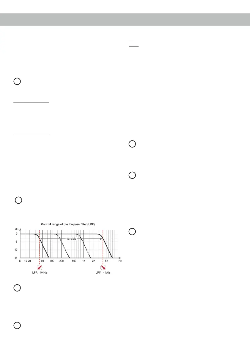
7
LPF
This control is used to adjust the crossover frequen-
cy of the lowpass lter of the channels C and D from
40 Hz to 4,000 Hz.
8
Speaker Output
Speaker outputs of the channels A - D to connect
speaker systems. The impedance per channel
must not be lower than 2 Ohms (4 Ohms in bridged
mode).
9
Power & Protect LED
The power and protect LED indicates the operating
mode of the amplier.
Green: The amplier is ready for operation.
Red: A malfunction has occurred. A malfunc-
tion may have different causes as the
HELIX M FOUR is equipped with sever-
al protection circuits. These protections
shut off the amplier in case of overheat-
ing, over- and undervoltage, short-circuit
on loudspeakers and false connection.
Please check for connecting failures such
as short-circuits, wrong connections,
wrong adjustments and over tempera-
ture. If the amplier does not turn on it is
defective and has to be sent to your local
authorized dealer for repair service. A de-
tailed description of the malfunction and
the purchase receipt has to be attached.
10
+12 V
Connect the +12 V power cable to the positive ter-
minal of the battery. Recommended cross section:
min. 10 mm² / AWG 8.
11
REM
The remote lead should be connected to the remote
output / automatic antenna (aerial positive) output
of the head unit / car radio. This is only activated
if the head unit / car radio is switched on. Thus the
amplier is switched on and off together with the
head unit / car radio. This input needn’t to be as-
signed if the Highlevel Input is used.
12
GND
The ground cable should be connected to a common
ground reference point (this is located where the
negative terminal of the battery is grounded to the
metal body of the vehicle) or to a prepared metal lo-
cation on the vehicle chassis i.e. an area which has
been cleaned of all paint residues. Recommended
cross section: min. 10 mm² / AWG 8.