24
Additional functions
1. Clipping LED
Normally the Clipping LED is o and only
lights up if one of the Line or Highlevel Inputs
is overdriven.
On (red): One of the analog signal inputs is
overdriven. Reduce the input sen-
sitivity using the three gain controls
until the LED goes out. How to
reduce the input sensitivity is de-
scribed on page 21 point 8.
Note: The LED has no function when using
one of the digital inputs.
2. Status LED
The Status LED indicates the operating mode
of the amplier and of its memory.
Green: Amplier is ready for operation.
Orange: Power Save Mode is active.
Red: Protection Mode is active. This may
have dierent root causes. The HELIX
P SIX DSP ULTIMATE is equipped with pro-
tection circuits against over- and undervolt-
age as well as overheating. Please check for
connecting failures such as short-circuits or
other wrong connections. If the amplier is
overheated the internal temperature protec-
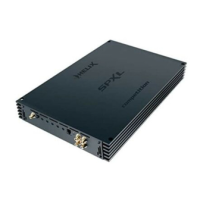
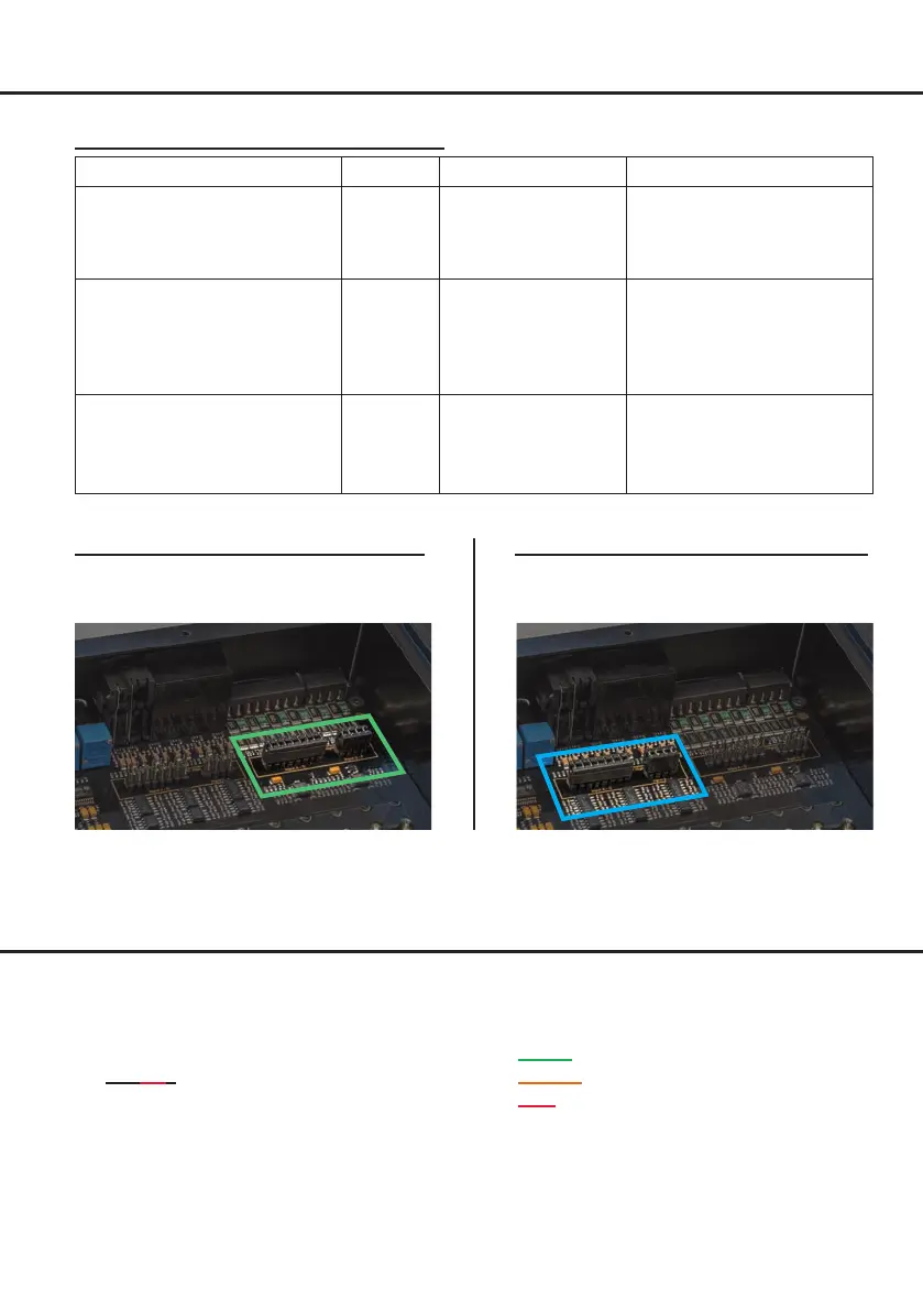
Fig. 1 – Low Voltage Range conguration: Fig. 2 – High Voltage Range conguration:
For further applications please contact your HELIX specialist dealer.
Value range: Highlevel 4 - 16 Volts
Lowlevel / Cinch 1 - 4 Volts
Value range: Highlevel 8 - 32 Volts
Lowlevel / Cinch 2 - 8 Volts
J 1
J 2
J 1
J 2
Examples for adjusting the input sensitivity:
Source Input Jumper positions
Position gain control
4- to 6-channel OEM radio
Up to 25 W RMS power per channel
at 4 Ω or up to 50 W RMS power
at 2 Ω
Highlevel
A - F
Low Voltage Range –
default jumper posi-
tions (see g. 1)
16 V (by default)
OEM-Radio with additional 4-
to 8-channel amplier
> 25 W and up to 200 W RMS power
per channel at 4 Ω or up to 400 Watt
2 Ω or 100 W at 8 Ω
Highlevel
A - F
High Voltage Range
(see g. 2)
Typically max. CCW position
4- to 6-channel aftermarket
radio with pre-amplier outputs
Up to 4 V RMS RCA / Cinch output
voltage
Lowlevel /
Cinch
A - F
Low Voltage Range –
default jumper
positions
(see g. 1)
Typically max. CCW position
for radios with 4 V output
voltage; max. CW position for
radios with 1 V output voltage
Hardware conguration
 Loading...