Installation
Connection of HELIX V EIGHT DSP to the head
XQLWFDUUDGLR
Caution: Carrying out the following steps will re-
quire special tools and technical knowledge. In or-
GHUWRDYRLGFRQQHFWLRQPLVWDNHVDQGRUGDPDJH
DVN\RXUGHDOHUIRUDVVLVWDQFHLI\RXKDYHDQ\TXHV
tions and follow all instructions in this manual (see
SDJH ,W LV UHFRPPHQGHG WKDW WKLV XQLW ZLOO EH
installed by an authorized HELIX dealer.
&RQQHFWLQJWKHSUHDPSOL¿HULQSXWV
8VH WKH FRUUHFW FDEOH 5&$ FLQFK FDEOH WR
FRQQHFW WKHVH LQSXWV WR WKH SUHDPSOL¿HU
ORZOHYHOFLQFKRXWSXWVRI\RXUFDUUDGLR(DFK
input can be assigned to any output using the
DSP PC-Tool software. The automatic turn-on
circuit does not work when using the pre-ampli-
¿HULQSXWV,QWKLVFDVHWKHUHPRWHLQSXWREM
KDV WR EH FRQQHFWHG WR DFWLYDWH WKH +(/,;
V EIGHT DSP.
Important: It is strictly forbidden to use the
Highlevel Input DQG SUHDPSOL¿HU LQSXWV Line
InputDWWKHVDPHWLPH7KLVPD\FDXVHVHYHUH
GDPDJHWRWKHSUHDPSOL¿HURXWSXWVRI\RXUFDU
radio.
2. Connecting the highlevel speaker inputs
7KH KLJKOHYHO ORXGVSHDNHU LQSXWV FDQ EH FRQ-
nected directly to the loudspeaker outputs of an
OEM or aftermarket radio using appropriate ca-
bles (loudspeaker cables with 1 mm² / AWG 18
PD[
We recommend the following channel assign-
ment if a common car radio will be connected
WRWKHDPSOL¿HU
&KDQQHO$ )URQWOHIW
&KDQQHO% )URQWULJKW
&KDQQHO& 5HDUOHIW
&KDQQHO' 5HDUULJKW
$FWXDOO\LWLVQRWPDQGDWRU\WRXVHDOOKLJKOHYHO
speaker inputs. If only two channels will be con-
nected we recommend to use the channels A
and B.
Make sure that the polarity is correct. If one
RU PRUH FRQQHFWLRQV KDYH UHYHUVHG SRODULW\ LW
PD\ DIIHFW WKHSHUIRUPDQFHRIWKHDPSOL¿HU ,I
this input is used the remote input (REMGRHV
QRWQHHGWR EHFRQQHFWHGDV WKHDPSOL¿HUZLOO
automatically turn on once a loudspeaker signal
LVUHFHLYHG
$GMXVWPHQWRIWKHLQSXWVHQVLWLYLW\
Attention: It is mandatory to properly adapt
the input sensitivity of the V EIGHT DSP to
the signal source in order to avoid damage
WRWKHDPSOL¿HU
6HYHUDO DGMXVWPHQWH[DPSOHVDUHOLVWHG LQ WKH
table on page 22.
,I\RXZDQWWRFKDQJHWKHLQSXWVHQVLWLYLW\XVH
the control 9 (see page 18 point 9; Input Sen-
sitivityDW¿UVW7KHVHWWLQJRIWKHFRQWURODIIHFWV
ERWKWKHORZOHYHODQGWKHKLJKOHYHOLQSXWV
,I WKH H[ IDFWRU\ VHQVLWLYLW\ UDQJH RI WKH ORZ-
OHYHO LQSXW 9ROWV UHVS KLJKOHYHO LQSXW
9ROWV PD\ QRW EH VXI¿FLHQW LW LV SRV-
sible to change it internally by repositioning
jumpers. Therefore dismantle the side panel
ZKHUH WKH86%LQSXW LV ORFDWHG E\UHPRYLQJ
the four screws (two Philipps head screws and
WZRDOOHQKHDG VFUHZV1RZ\RX FDQSXOORXW
the bottom plate and get access to the jumpers.
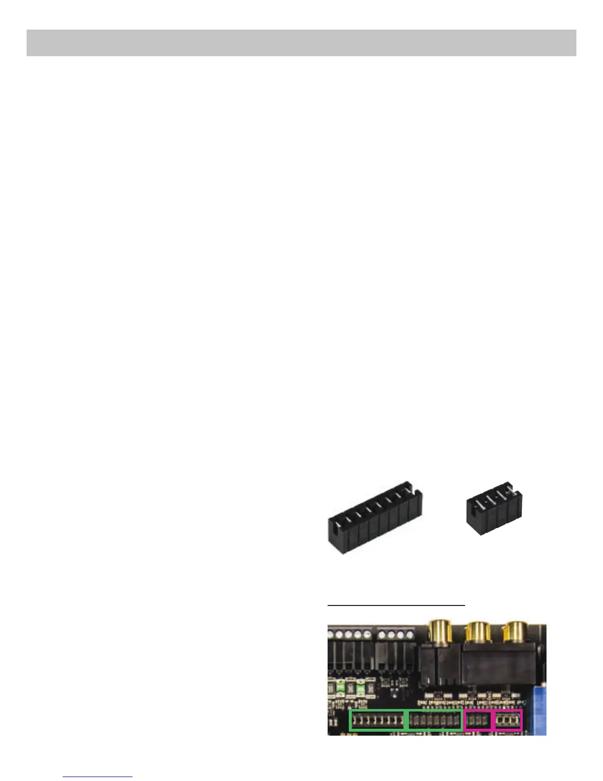
The long jumper (
Jumper ASLQVDIIHFWVWKH
channels A - D and the short jumper (
Jumper B,
SLQVWKHFKDQQHOV(DQG),QVLGHWKHGHYLFH
there are two plug positions for each Jumper.
7KHGLIIHUHQWSOXJSRVLWLRQVDUHH[SODLQHGLQWKH
following:
Overview plug-in positions:
Jumper A
Jumper B
A2 B1A1 B2
19
 Loading...