12
WS1 & 1.25 Manual Page 31
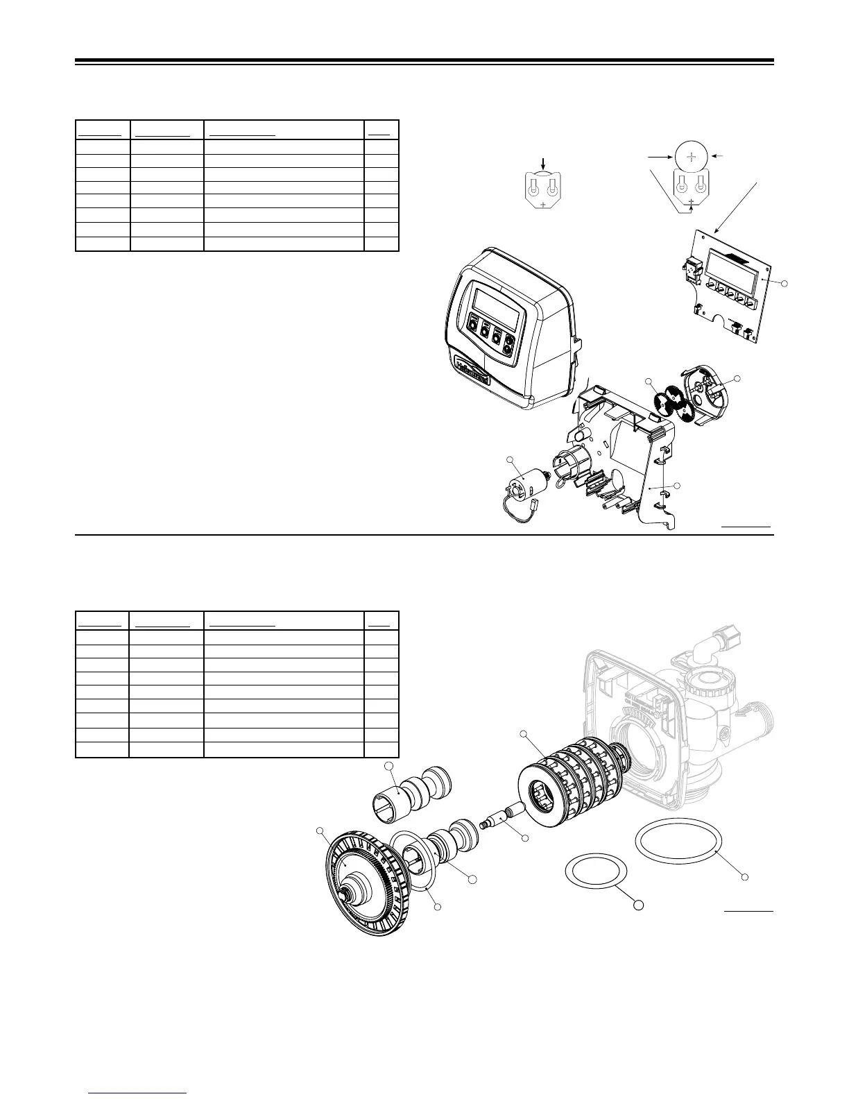
Front Cover and Drive Assembly
* Drawing number parts 2 through 6 may be purchased as a complete assembly, part V3002.
Drawing No. Order No. Description Quantity
1 V3175-01 WS1 Front Cover ASY 1
2 V3107-01 WS1 Motor 1
3 V3106-01 WS1 Drive Bracket&Spring Clip 1
4 V3108-09BOARD WS1 PC Board with Battery REPLACE 1
5 V3110 WS1 Drive Gear 12x36 3
6 V3109 WS1 Drive Gear Cover 1
V3002 WS1 Drive ASY *
Not Shown V3186 WS1 AC Adapter 110V-12V 1
Not Shown
V3186 WS1 AC ADAPTER 110V-12V
1
V3186EU WS1 AC ADAPTER 220-240V-12V EU
V3186UK WS1 AC ADAPTER 220-240V-12V UK
V3186-01 WS1 AC ADAPTER CORD ONLY
Battery Fully Seated
When replacing the battery, align
positives and push down to fully seat.
Correct
Battery
Orientation
Battery replacement is
3 volt lithium coin cell
type 2032.
FRONT COVER AND DRIVE ASSEMBLY
DRIVE CAP ASSEMBLY, DOWNFLOW PISTON, REGENERANT PISTON
AND SPACER STACK ASSEMBLY
1 102548 Spacer Stack Assy 1
2 101613 Drive Cap Assy. 1
3 102167 O-Ring 228 1
4a 102292 Piston Downow Assy. 1**
4b 102297 Piston Upow Assy. 1
5 102296 Regenerant Piston 1
6 102192 O-ring 337-tank 1
7 102165 O-ring distributor tube 1
Not Shown 102892 Service Wrench 1
QTY.
ITEM NO.
ORDER NO.
DESCRIPTION
*102292 is labeled with DN and 102297 is labeled with UP.
Note: The regenerant piston is not used in backwash only applications.
**Standard Option.
After completing any valve maintenance involving the drive assembly or the
drive cap assembly and pistons, press and hold NEXT and REGEN buttons
for 3 seconds or unplug power source jack from the printed circuit board (black
wire) and plug back in. This resets the electronics and establishes the service
piston position. The display should ash all wording, then ash the software
version (ex: 154) and then reset the valve to the service position.
Do not use vaseline, oils, other hydrocarbon lubricants or spray silicone anywhere. A silicon lubricant may be used on black o-rings but is not necessary. Avoid any
type of lubricants, including silicone, on red or clear lip seals.
After completing any valve maintenance involving the drive assembly or the drive cap assembly and pistons, press and hold NEXT and REGEN buttons for 3 seconds
or unplug power source jack from the printed circuit board (black wire) and plug back in. This resets the electronics and establishes the service piston position. The
display should ash all wording, then ash the software version (ex: 154) and then reset the valve to the service position.
Figure 13
Figure 14
1 109380 Black Cover Assy w/ Label 1
2-6 101610 Drive Assy. *
2 102096 Motor 1
3 101262 Drive Bracket & Spring Clip 1
4 109379 PC Board 1
5 101746 Drive Gear 12x36 3
6 101459 Drive Gear Cover 1
Not Shown 102653 Transformer 110V-12V 1
QTY.
ITEM NO.
ORDER NO.
DESCRIPTION
7
REV.DWG. NO.
REVISIONS
PROPRIETARY AND CONFIDENTIAL:
THE INFORMATION CONTAINED IN THIS
DRAWING IS THE SOLE PROPERTY OF
HELLENBRAND INC. ANY REPRODUCTION
IN PART OR AS A WHOLE WITHOUT T HE
WRITTEN PERMISSION OF HELLENBRAND INC.
IS PROHIBITED.
DWG DESCRIPTION:ENG APPR.DRAWN DATE
DIMENSIONS ARE IN INCHES
TOLERANCE: X" +/- 2"
Hellenbrand
DATE BY COMMENTSNO.