13
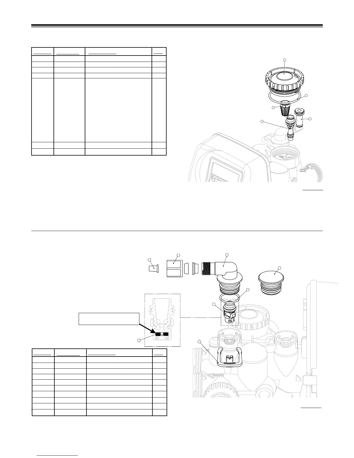
INJECTOR CAP, INJECTOR SCREEN, INJECTOR, PLUG AND O-RING
REFILL AND REFILL PORT PLUG
1 101375 Injector Cap 1
2 102159 O-ring 135 1
3 102457 Injector Screen 1
4 102319 Injector Assy. Z Plug-Filter 1
5 101825 Injector Assy. A Black 1
101826 Injector Assy. B Brown
101827 Injector Assy. C Violet
101828 Injector Assy. D Red
101829 Injector Assy. E White
101830 Injector Assy. F Blue
101831 Injector Assy. G Yellow
101832 Injector Assy. H Green
101833 Injector Assy. I Orange
101834 Injector Assy. J Light Blue
101835 Injector Assy K Light Green
Not Shown 106767 O-ring 011 *
Not Shown 106768 O-ring 013 *
QTY.
ITEM NO.
ORDER NO.
DESCRIPTION
* The injector plug and the injector each contain one 011 (lower) and 013
(upper) o-ring.
See system specication, injector color on page 18 for current injector.
Note: For upow position, injector is located in the up hole and injector
plug in the down hole. For a lter that only backwashes injector plugs are
located in both holes.
The nuts and caps are designed to be unscrewed or tightened by hand or with the special plastic wrench. If necessary a pliers can be used to unscrew the nut or
cap. Do not use a pipe wrench to tighten or loosen nuts or caps. Do not place screwdriver in slots on caps and/or tap with a hammer.
Do not use pipe dope or other sealants on threads. Teon tape must be used on threads of the 1” NPT connection and on the threads for the drain line connection.
Teon tape is not necessary on the nut connection nor caps because of o-rings seals.
Figure 15
Figure 16
Proper ow control orientation,
rounded edge & text this side.
*Assembly includes item #8.
**This part is required for backwash only systems.
1 102322 Rell Port Plug Assy.** 1
2 101414 Elbow Locking Clip 1
3 101868 Polytube Insert 3/8 1
4 102130 Nut 3/8 1
5-8 103589 3/8” Rell Elbow Assembly 1
5 101620 Elbow Cap 3/8 1
6 102153 O-ring 019 1
7 102418* Rell Flow Cntrl Retainer Assy. 1
8 102421 Rell Flow Control Button 1
Not Shown 101617 1/2” Elbow w/Nut & Insert 1
QTY.
ITEM NO.
ORDER NO.
DESCRIPTION