13
5 6
7 8
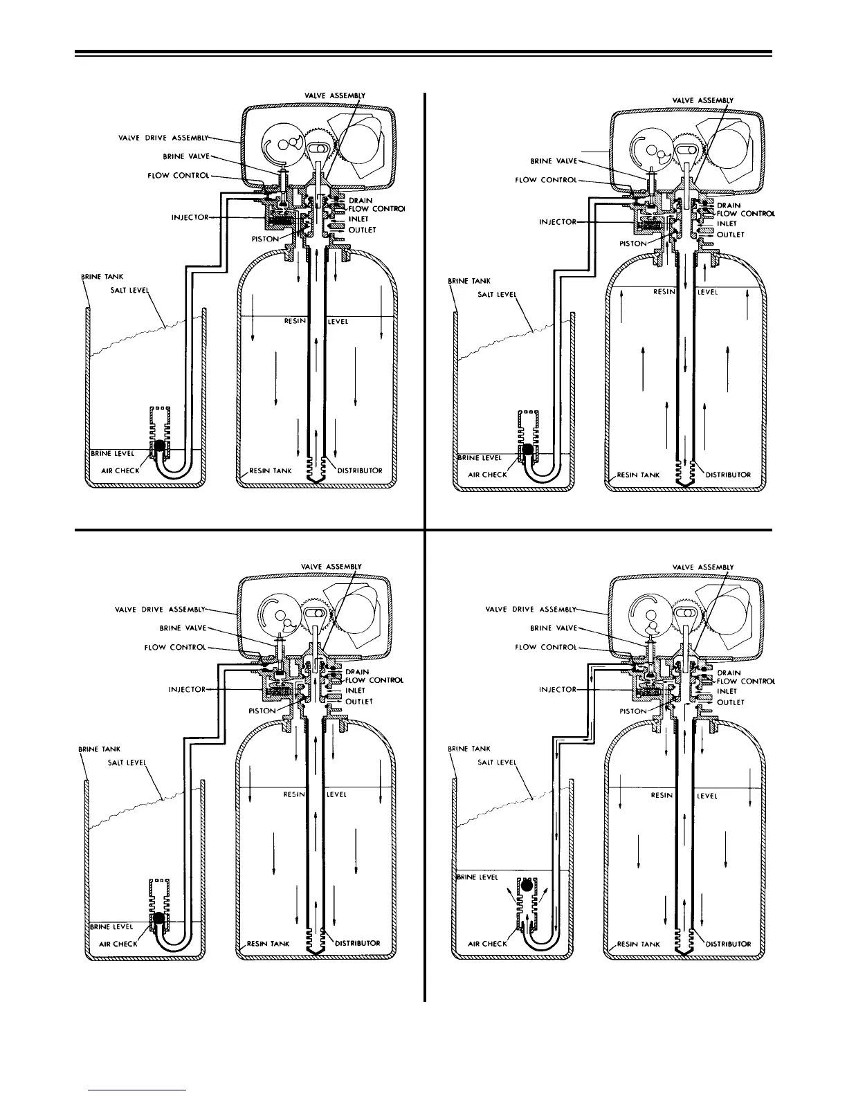
Brine Tank
Fill Position
Settling Rinse
Position
Rapid
Rinse Position
Slow Rinse
Position
4 To 24 Minutes Adjustable Cycle
Hard water enters the unit at the valve inlet - ows around the lower piston groove and
lower piston land - down thru the center tube and out the distributor - up thru the resin -
thru the top of tank passage - around the upper piston groove and out the drain line.
Hard water enters the unit at the valve inlet - ows around the lower piston groove - down
thru the top of tank passage - downward thru the resin - up the distributor tube - thru the
center hole in the piston - over the top edge of the piston and out the drain line.
Hard water enters the unit at the valve inlet - ows around the lower piston groove - thru
the injector throat - thru the brine valve and ow control to ll the brine tank. Hard water
also ows around the lower piston groove - thru the passage to the top of tank - down
thru the resin and enters the distributor as conditioned water. The conditioned water
ows up thru the center tube to the valve outlet.
Last Portion of 50 Minute Fixed Cycle
After all the brine has been drawn from the brine tank, hard water continues to enter
thru the valve inlet - ows around the lower piston groove - thru the nozzle and orice
- down thru the resin and into the distributor - up thru the center tube - thru the center
hole in the piston and out the drain line.
VALVE DRIVE ASSEMBLY
10 minutes with standard piston
7 minutes with low water use piston
5 minutes with standard piston
0 minutes with low water use piston
 Loading...