14
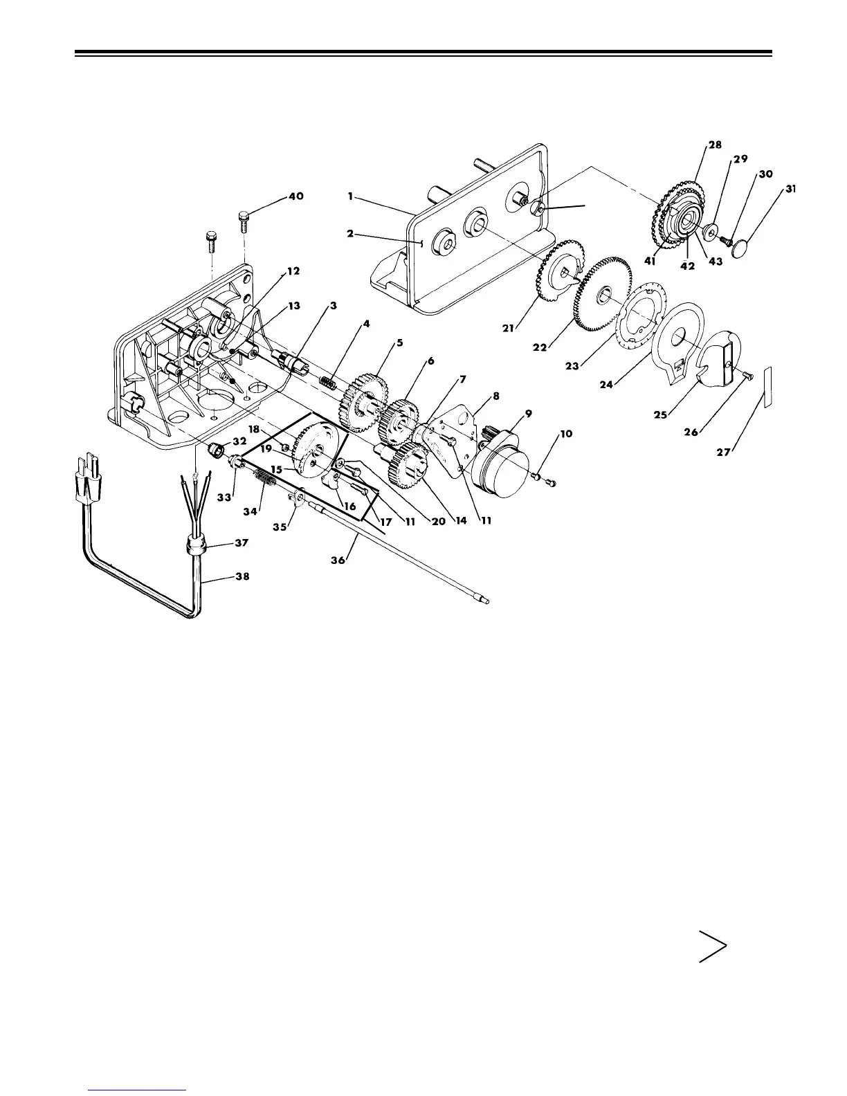
CONTROL VALVE POWERHEAD ASSEMBLY
DEMAND REGENERATION MODEL
ITEM NO. NO. REQ'D
PART NO. DESCRIPTION
1 ......... 1 ................ 102219 ........Drive Panel
2 ......... 1 ................ 101967 ........Label
3 ......... 1 ................ 106492 ........Idler Shaft
4 ......... 1 ................ 106496 ........Spring - Idler
5 ......... 1 ................ 102306 ........Idler Gear
6 ......... 1 ................ 106493 ........Drive Gear
7 ......... 1 ................ 102873 ........Curved Washer
8 ......... 1 ................ 102307 ........Motor Mounting Plate
9 ......... 1 ................ 102094 ........Motor
10 ......... 3 ................ 102482 ........Screw – Motor Mounting
11 ......... 4 ................ 102468 ........Screw – Mounting
12 ......... 2 .............49-14457 ........Detent Spring
13 ......... 2 ................ 106494 ........Ball – 1/4" Diameter
14 ......... 1 ................ 101741 ........Main Gear & Shaft
15 ......... 1 ................ 101356 ........Brine Cam
16 ......... 1 .....................................Cam Segment (Sold with #15)
17 ......... 1 .............49-11980 ........8-32x5/8" Screw
18 ......... 1 .............49-11081 ........Hex Nut
19 ......... 1 ................ 101978 ........Salt Label, 3-16
20 ......... 1 ................ 102866 ........#10 Washer
21 ......... 1 ................ 101745 ........Cycle Actuator Gear
22 ......... 1 .............49-13009 .......24 Hour Gear
23 ......... 1 ................ 101956 ........24 Hour Label
24 ......... 1 ................ 101486 ........Valve Position Dial - Std Piston
......... 1 .............49-14278 ........Valve Position Dial - Low Water
Piston
ITEM NO. NO. REQ'D
PART NO. DESCRIPTION
25 ......... 1 ................ 101947 ........Knob
26 ......... 1 ................ 102462 ........Screw
27 ......... 1 ................ 101964 ........Label on Control Knob
28 ......... 1 ................ 102888 ........Program Wheel Assembly
29 ......... 1 ................ 102420 ........Program Wheel Retainer
30 ......... 1 ................ 102461 ........Screw, Top Collector
31 ......... 1 ................ 101953 ........Cover Label
32 ......... 1 ................ 102235 ........Drive Pinion
33 ......... 1 ................ 101416 ........Clutch
34 ......... 1 ................ 102554 ........Spring, Meter Clutch
35 ......... 1 ................ 102403 ........Spring Retainer
36 ......... 1 ................ 101342 ........Flexible 8.25" Cable
37 ......... 1 ................ 102566 ........Strain Relief
38 ......... 1 .............49-11842 ........Power Cord
39 ......... 2 ................ 103087 ........Wire Nut
40 ......... 2 ................ 102467 ........Screw – Drive Mounting
41 ......... 1 .... Consult Dealer ........Gallon Label
42 ......... 1 .... Consult Dealer ........Hardness "K" Label
43 ......... 1 .... Consult Dealer ........People Label
44 ......... 1 ................ 101440 ........Cover
45 ......... 1 ................ 100843 ........Label Front Cover
46 ......... 1 ................ 101977 ........Label Back Cover
(1-43) ........ 1 ................ 102344 ........Complete Assembly
47 ......... 1 ................ 101357 ........Brine Cam Assembly
48 ......... 1 .............49-14252 ........Meter Clutch Cap
Not
Shown
47
48
 Loading...