5
EN
• a omnipolar switch with minimum between-con-
tacts aperture of the overvoltage category III (4000
V),
sized to the load and conforming to current
legal regulations, is fi tted between the appliance
and the mains in the direct connection to the
mains;
• the omnipolar switch used for connection is easy
to reach when the appliance is installed;
• the yellow/green earth wire is not interrupted
by the switch;
• the power supply, when the appliance is operat-
ing, must not deviate from the rated voltage value
by ±10%;
• make sure that after inserting the power supply
cord into the terminal block it does not come into
contact with any of the cooking range’s hot parts.
• if the supply cable is damaged then it must be
replaced by the manufacturer or by your tech-
nical support or by a qualified person to avoid
any risk.
Connection to the water mains
(for ovens predisposed to humidifi er solenoid-valve)
The appliance must be fed with softened drinking
water, with pressure in the range from 100 to 200 kPa
(1.0
- 2.0 bar). Water must have hardness from 0.5°F to
3°F (it is suggstible to use a softener as to avoid the
malfunction of the fan, the breakage of the heating
element and to reduce the formation of lime inside
the cooking chamber). Connection to the water
mains should be made through the threaded 3/4”
solenoid-valve on the rear (on the bottom) of the
appliance, fi tting in between a mechanical fi lter and
an on/off tap (before you connect the fi lter, allow
a certain quantity of water to fl ow out in order to
drain any waste from the pipe).
Connection to water tank
(for ovens predisposed to water pump)
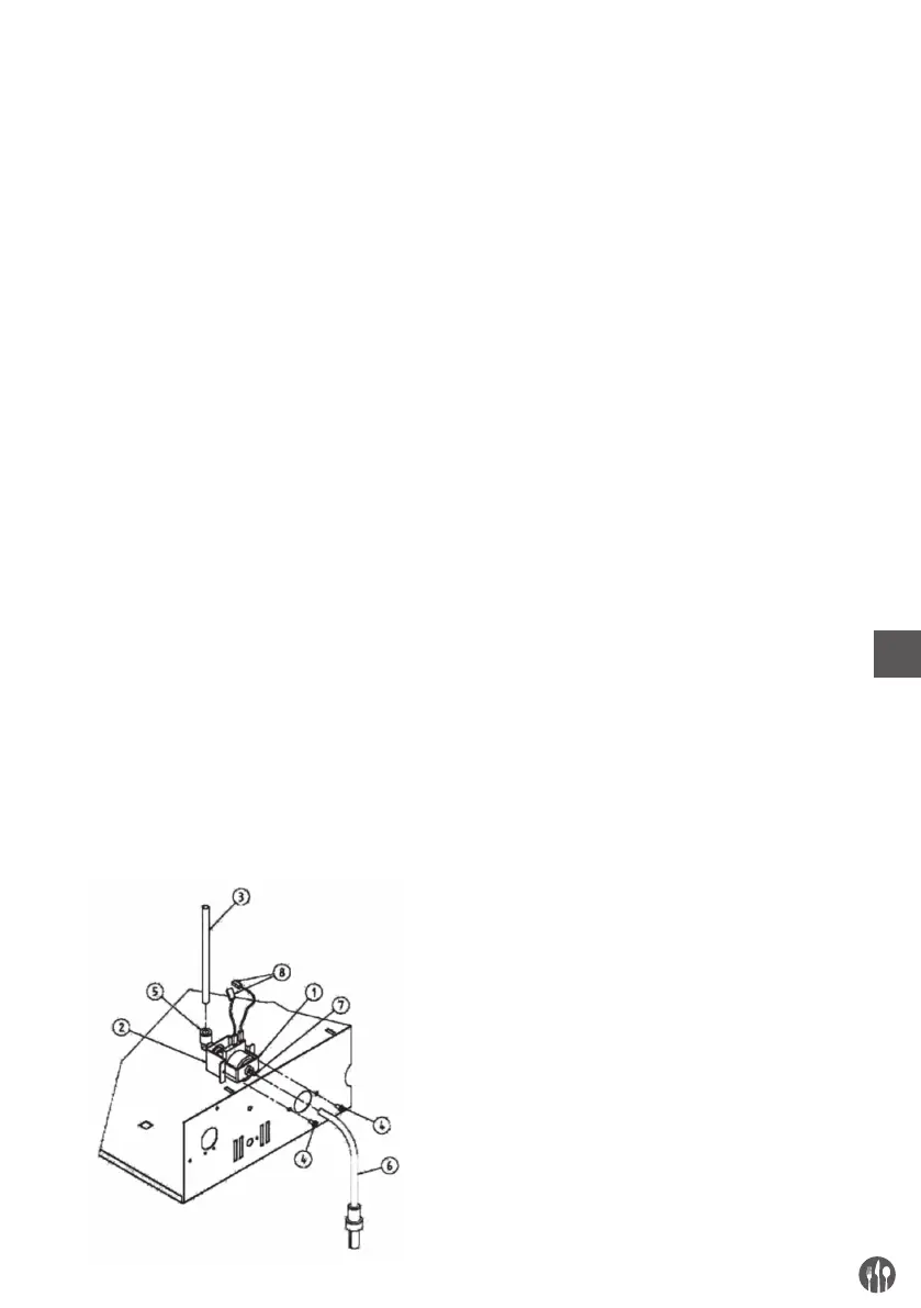
To replace electrovalve with water pump (in ovens
with
optional predisposition to pump), follow the
steps below listed (image 1):
1. Remove back cover from oven.
2. Disconnect wiring cables from electrovalve.
3. Disconnect water tube (3) from electrovalve,
pressing e keeping pressed the edge of black
linking (quick insertion).
4. Remove the electrovalve unscrewing the screw
that fi x it to oven’s frame.
5. Fix the pump (1) to the frame with the appropri-
ate support (2) and the two screws (4) included.
6. Connect the cables previously disconnected from
electrovalve to pump.
7. Connect the tube previously disconnected from
electrovalve to pump’s linking.
8.
Connect the tube (6) with fi lter and ballast (includ-
ed
in “Pump kit”) to pump’s apron (7).
9. Replace back cover.
Warning:
To avoid limestone buildup into the cooking chamber,
we suggest to fi ll the water tank with decalcifi ed water.
Check water level in the tank before activating the
pump and during its functioning. If pump works with-
out water in the tank, what occurs is abnormal noise
at first and then its breakage.
Fig. 1