Alignment & Adjustments 28 17730-241
AR2
™
6. Deflate the suspension by using one of the following methods, if the vehicle:
■
Method 1 — is equipped with a suspension dump system in the cab, deflate the suspen-
sion air system by using the cab dump valve control
■
Method 2 — is not equipped with a suspension dump system, detach both the upper rub-
ber grommets of the height control valve linkages from the height control valve arms and
exhaust the suspension system air by lowering the height control valve arms, see Figure 7-1
7. Inflate the suspension by using one of the following methods, if the vehicle:
■
Method 1 — is equipped with a suspension dump system in the cab, inflate the suspension
air system by using the cab dump valve control. Allow the suspension system to inflate
■
Method 2 — is not equipped with a suspension dump system, raise the height control
valve arms and attach the upper rubber grommets of the height control valve linkage to
the height control valve arms. Allow the suspension system to inflate
8. Locate the wheel end where the height control valve is installed.
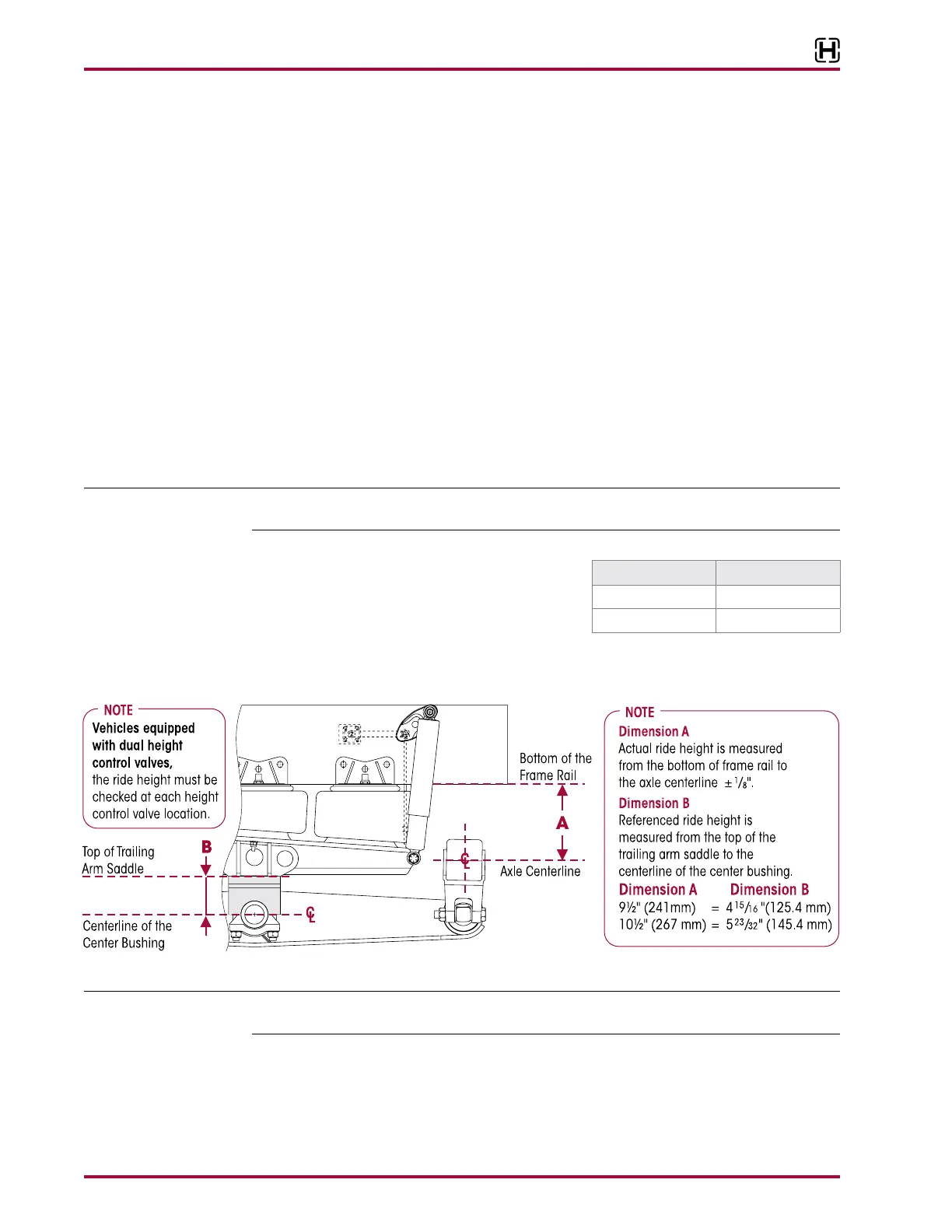
9. Measure the actual suspension ride height, (Dimension A) the distance from the bottom of
the frame rail to the axle centerline, see Figure 7-2.
10. Measure the referenced ride height (Dimension B) from the top of the of the trailing arm
saddle to the centerline of the center bushing, see Figure 7-2.
A vehicle equipped with dual height control valves must measure the ride height at each height
control valve location.
11. Compare the actual (Dimension A) ride height to
the (Dimension B) for your suspension in Table
7-1.
12. If the ride height is correct, no further adjust-
ment is necessary. If incorrect, then height control valve adjustment is required. Refer to the
Adjustment Procedure in this section.
When inspecting or setting the ride height on a vehicle, it is recommended to have a load on the
vehicle. Loading the vehicle to its normal operating condition increases ride height setting accuracy.
1. Drive the vehicle onto a level surface.
2. Relax the suspension by slowly moving the vehicle back and forth several times in a straight
line without using the brakes. This will slacken or loosen the suspension as the vehicle is posi-
tioned. End with all wheels positioned straight ahead. Roll to a stop without the brakes being
applied. set the parking brake.
3. Chock front wheels of the vehicle.
A B
9½" (241 mm) 4
15
⁄16" (125.4 mm)
10½" (267 mm) 5
23
⁄32" (145.4 mm)