Component Replacement 56 17730-241
AR2
™
14. Install the saddle caps, refer to Saddle Cap Assembly in this section.
15. Install the tires.
16. Remove the supports from the drive axles and lower the vehicle onto the ground.
17. Remove the wheel chocks.
AR2 SUSPENSIONS INCORPORATE TORQUE RODS FOR VEHICLE STABILITY. IF THESE COMPONENTS
ARE DISCONNECTED OR ARE NON-FUNCTIONAL, THE VEHICLE SHOULD NOT BE OPERATED. FAILURE
TO DO SO CAN RESULT IN ADVERSE VEHICLE HANDLING, ADVERSE VEHICLE HANDLING, POSSIBLE TIRE
CONTACT WITH THE FRAME, PREMATURE COMPONENT DAMAGE, OR SEVERE PERSONAL INJURY.
1. Chock the front wheels
of the vehicle.
2. Support the pinion on
the axle being serviced.
To remove all the load from
the longitudinal torque rods,
raise or lower the pinion as
needed. This will ease the
removal of the longitudinal
torque rod.
Prior to disassembly of the longitudinal torque rods, note the quantity and orientation of the lon-
gitudinal torque rod shims. It is required that the longitudinal torque rod shims are installed in the
same orientation and location as removed to preserve the existing alignment.
3. Remove the torque rod mounting fasteners and shims (if equipped).
4. Remove the fasteners that connect the longitudinal torque rod to the cross member and
axle brackets.
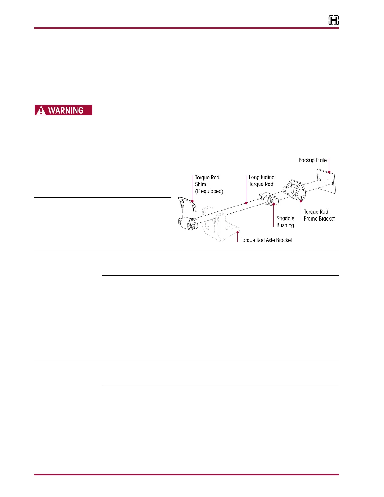
5. Remove longitudinal torque rods, see Figure 8-34.
1. Install longitudinal torque rods.
2. Install new fasteners and any shims (that were equipped) to the cross member and torque
rod axle brackets.
Hendrickson recommends the use of grade 8 bolts and grade C locknuts. If flange head bolts
and locknuts are not used then hardened structural washers must be used under bolt heads
and locknuts.
3. Tighten all fasteners to vehicle manufacturer’s torque specifications.
4. Verify proper pinion angle, and correct with drop in shims between the torque rod bar pin
and the cross member or torque rod axle bracket depending on the direction of adjustment
needed. Contact the vehicle manufacturer for proper pinion angle specifications.
5. Remove wheel chocks.