Component Replacement 58 17730-241
AR2
™
5. Install the two (2)
5
⁄8" fasteners through the torque rod bar pin and shims as per prior to
removal.
6. Install transverse torque rod frame bracket, spacer plate, and backup plate as per prior to
removal.
Hendrickson recommends the using Grade 8 bolts and Grade C locknuts for all torque rod
attachments.
7. Prior to tightening torque rod fasteners ensure the vehicle is at the proper ride height, refer to
Ride Height in the Alignment & Adjustment section of this publication.
8. Tighten the taper pin to axle bracket at the 1
1
⁄4" locknut to 200 ± 25 foot pounds torque.
9. Tighten the
5
⁄8" bolt head to torque rod to 75 ± 15 foot pounds torque.
10. Tighten the two (2)
5
⁄8" torque rod-to-frame mounting fasteners to 185 ± 25 foot pounds
torque and at the
5
⁄8" bolt head to 200 ± 25 foot pounds torque, see Figure 8-35.
11. Check the lateral alignment, if not within the vehicle manufacturer’s specified range, a lat-
eral alignment is necessary. Refer to the Lateral Alignment in the Alignment & Adjustments
section of this publication.
12. Remove the wheel chocks.
■
A vertical press with a capacity of at least
10tons
■
Shop made receiving tool and installation /
removal tool, refer to the Special Tools section of
this publication for more information
■
Funnel Tools, refer to the Special Tools section of this publication for more information
■
, Tool Part No. 66086-001L
■
, Tool Part No. 66086-000L
1. Remove torque rods as detailed in Torque Rod Disassembly instructions in this section.
DO NOT USE HEAT OR USE A CUTTING TORCH TO REMOVE THE BUSHINGS FROM THE TORQUE ROD. THE
USE OF HEAT WILL ADVERSELY AFFECT THE STRENGTH OF THE TORQUE ROD, HEAT CAN CHANGE THE
MATERIAL PROPERTIES. A COMPONENT DAMAGED IN THIS MANNER CAN RESULT IN ADVERSE VEHICLE
HANDLING AND POSSIBLE PERSONAL INJURY OR PROPERTY DAMAGE.
2. Support the torque rod end tube centered on the receiving tool. Be sure the torque rod is
squarely supported on the press bed for safe ty.
3. Push directly on the straddle mount bar pin, until the top of the pin is level with the top of
torque rod end tube. Place the push out tool directly on top of the bar pin and press until the
bushing clears the torque rod end tube.
4. Remove the fasteners from the tapered bar pin bushing, and support the torque rod end on
the receiving tool with the tapered stud pointing up and the end tube centered on the tool. Be
sure the torque rod is squarely supported on the press bed for safety.
5. Push directly on the tapered stud until the bushing clears the torque rod end tube.
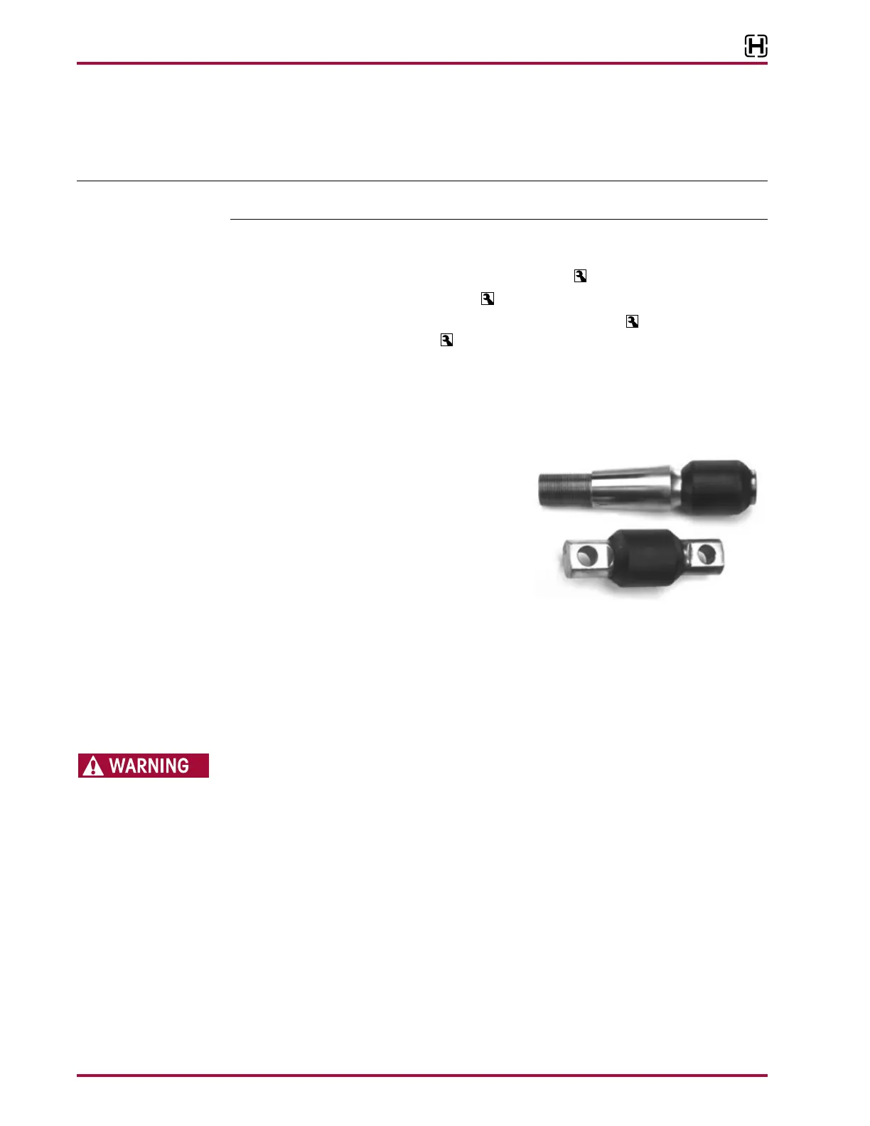
Straddle Pin Bushing
Taper Pin Bushing