17730-241 43 Component Replacement
AR2
™
1. Install the air fittings into the new
height control valve using Teflon
thread seal.
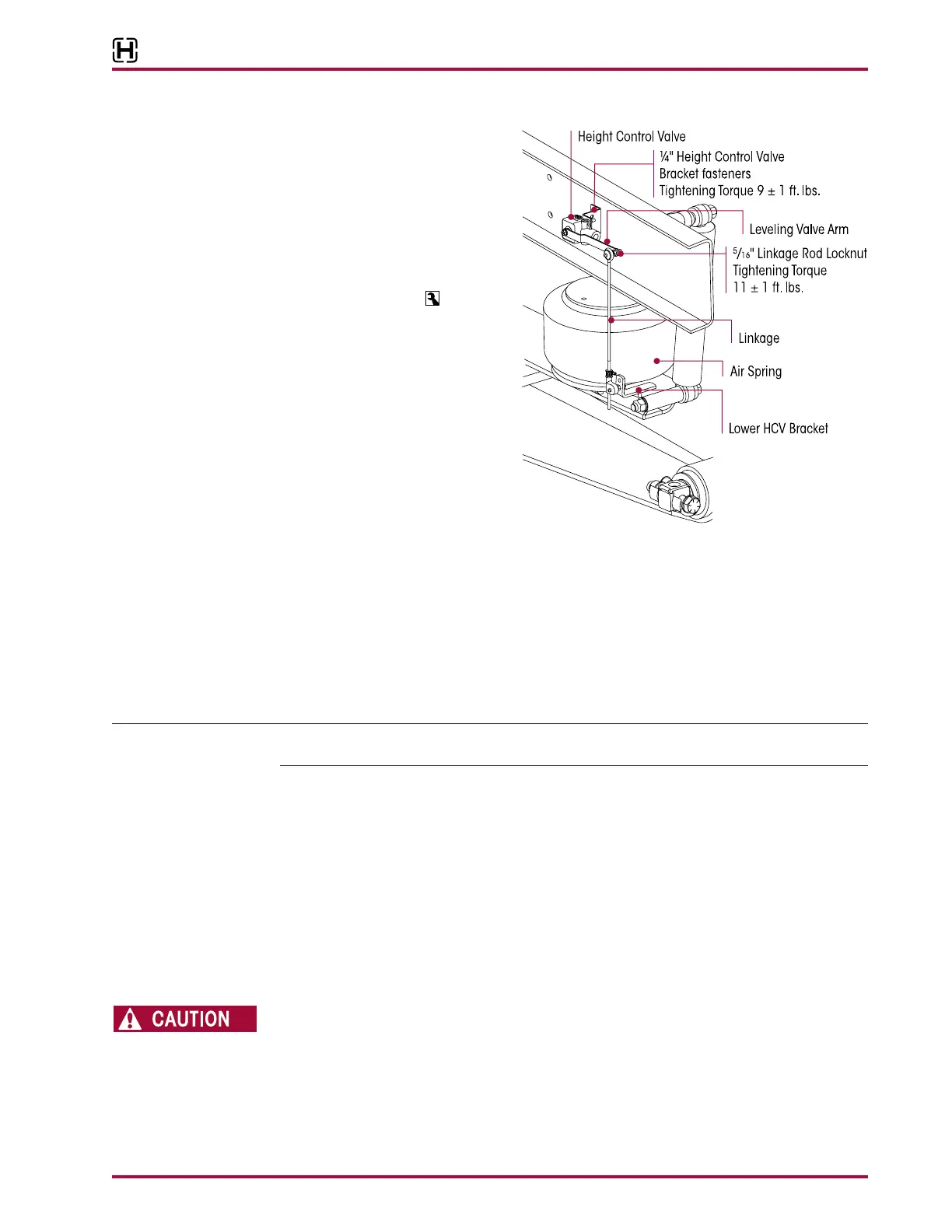
2. Install the height control valve to
the frame mounting bracket by
attaching the ¼" washers and
locknuts. Tighten to
9±1 foot
pounds torque, see Figure 8-8.
3. Install the air lines to the height
control valve. Refer to the
Plumbing Diagram section of this
publication.
4. See Air Spring Cautions and
Warnings in the Important Safety
Notice section of this publication
prior to deflating or inflating the
suspension system.
5. Inflate the suspension by con-
necting the height control valve linkage(s) to the leveling valve arm(s).
6. Verify the air springs inflate uniformly without binding and that the vehicle air system is at the
correct operating air pressure.
7. Verify proper ride height, refer to Ride Height in the Alignment & Adjustments section of this
publication.
8. Remove the wheel chocks.
It is recommended to remove both equalizing beams and the cross tube as a group even if only
one (1) equalizing beam needs service.
1. Chock the wheels of the steer axle.
2. Raise and support the drive axles with safety stands.
3. Remove the tires.
4. Support the pinion angle of the drive axles to prevent axle movement during service.
5. Remove the saddle cap fasteners from both inboard and outboard sides of both equalizing
beam’s center bushings.
6. Remove the saddle caps, see Figure 8-9.
7. Raise the vehicle’s frame just enough to create a ½" (13 mm) gap between the saddles and
the center bushings. Support the vehicle’s frame at this height.
THE WEIGHT OF THE EQUALIZING BEAM ASSEMBLY IS APPROXIMATELY 155 POUNDS. PRIOR TO
REMOVING THE BEAM END FASTENERS FROM THE EQUALIZING BEAM, SUPPORT THE END OF THE
EQUALIZING BEAM TO PREVENT FROM DROPPING. CARE SHOULD BE TAKEN AT REMOVAL AND
INSTALLATION TO PREVENT PERSONAL INJURY OR DAMAGE TO COMPONENTS.