Component Replacement 44 17730-241
AR2
™
8. Support both equalizing beams
with a floor jack.
9. Remove and discard beam end
attaching fasteners.
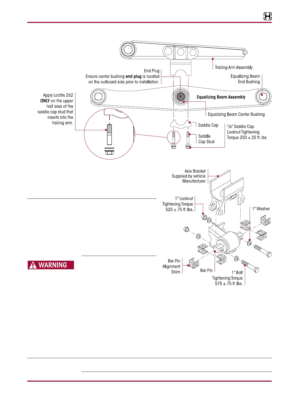
Prior to disassembly of the equalizing
beam bar pin fasteners, note the orien-
tation of the bar pin alignment shims,
see Figure 8-10. It is required that the
bar pin alignment shims are installed
in the same orientation and location
as removed to preserve the existing
vehicle alignment. Improper vehicle
alignment can increase tire wear.
PRIOR TO REMOVING BOTH EQUALIZING
BEAMS, SUPPORT THE PINION OF
EACH DRIVE AXLE. FAILURE TO DO SO
CAN RESULT IN PERSONAL INJURY OR
ALLOW THE AXLES TO SHIFT MAKING
REASSEMBLY MORE DIFFICULT.
10. Slowly lower the floor jacks and remove the equalizing beams from the axle brackets.
11. Slide the equalizing beams off the cross tube and out from under the vehicle.
12. Remove the floor jacks from under the equalizing beams.
1. Position the equalizing beams under the axles with a floor jack under the center of each
equalizing beam.
2. Install the cross tube into the center bushing of each equalizing beam.
Ensure the equalizing beam’s center bushing end plug is located on the outboard side, see
Figure 8-11.