Component Replacement 38 17730-241
AR2
™
13. Tighten the saddle cap lock-
nuts to 250 ± 25 foot
pounds torque.
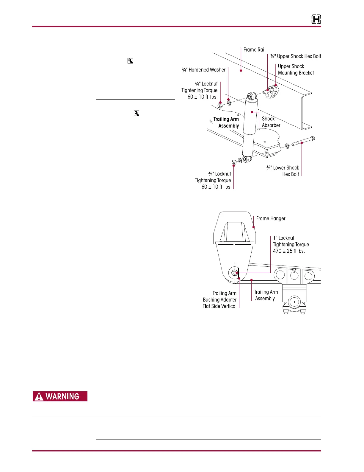
Ensure the trailing arm bushing
adapter flats are vertical, see
Figure 8-4.
14. Tighten the bushing adapter
locknuts to
470 ± 25 foot
pounds torque, see Figure 8-2.
15. See Air Spring Cautions and
Warnings in the Important
Safety Notice section of this
publication prior to deflating
or inflating the suspension
system.
16. Connect the height control
valve linkage(s) to the height
control valve arm(s) to inflate
the suspension.
17. Inflate the suspension slowly and verify
that the air spring bladder inflates uni-
formly without binding.
18. Verify proper ride height, refer to Ride
Height in the Alignment & Adjustments
section of this publication.
19. Remove the wheel chocks.
TRAILING ARM BUSHING
■
A shop press with a capacity of at least 100 tons
■
Adapter set tool — (Hendrickson Part No. 66086-102) – Refer to Special Tools section of this
publication for the tools to remove and install the trailing arm bushings
■
Receiving tool — The receiving tool is a shop made tool which completely supports the beam
hub being serviced and is tall enough to receive the bushing as it is being pressed in or out,
see Special Tools section of this publication
DISCARD USED FASTENERS. ALWAYS USE NEW FASTENERS TO COMPLETE A REPAIR. FAILURE TO DO SO
COULD RESULT IN FAILURE OF THE PART OR MATING PARTS, ADVERSE VEHICLE HANDLING, PERSONAL
INJURY, OR PROPERTY DAMAGE.
Hendrickson recommends the use of Grade 8 bolts and Grade C locknuts. If flange head bolts
and locknuts are not used then hardened structural washers must be used under bolt heads
and locknuts.