17730-241 55 Component Replacement
AR2
™
CHECK TO ENSURE PROPER ALIGNMENT OF TOOLING
ADAPTERS WITH EQUALIZING BEAM COMPONENTS
BEFORE APPLYING FULL HYDRAULIC PRESSURE WITH
A SHOP PRESS.
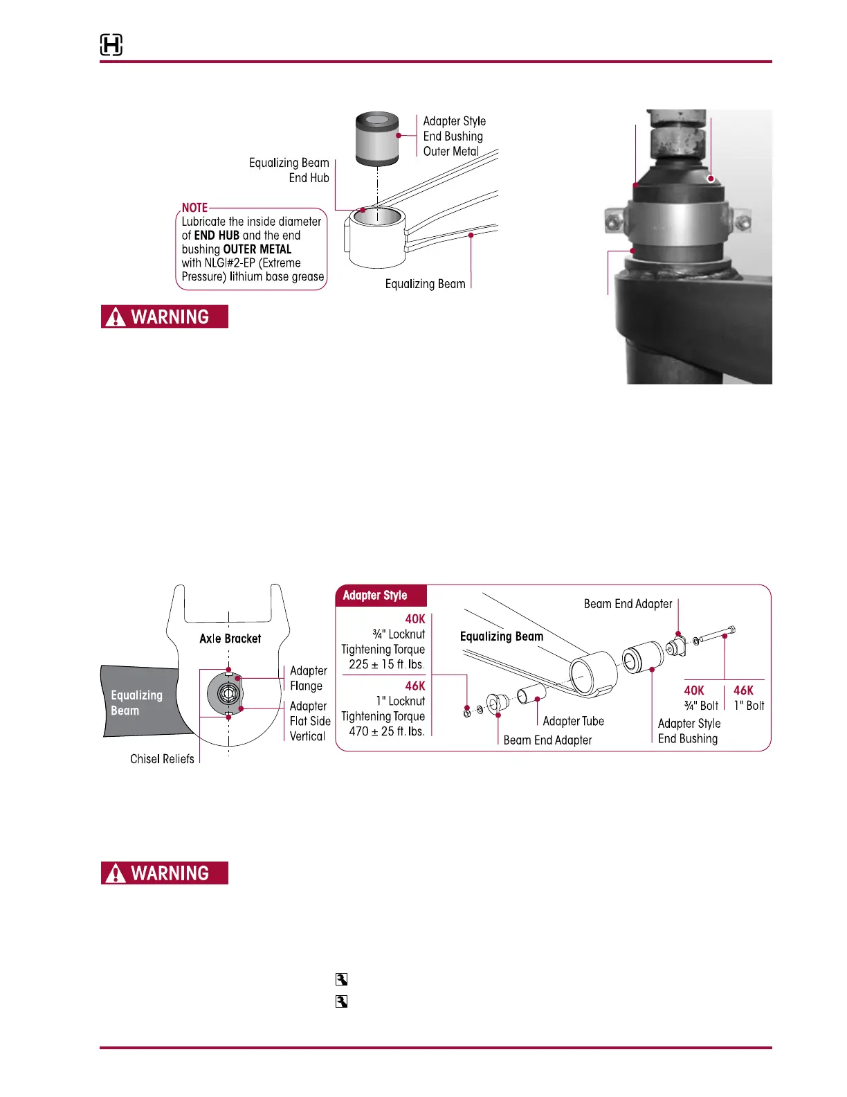
5. Apply hydraulic force and press the new bush-
ing into place. The bushing will be completely seated when the clamp makes contact with the
beam face.
6. Using the floor jacks, slowly raise both equalizing beams and cross tube as an assembly
into the axle brackets. Ensure that each equalizing beam end bushing correctly engages
the axle bracket.
7. Install one (1) adapter through the axle bracket leg at the wheel side, into the beam
end bushing.
8. Install the other adapter through the axle bracket leg at the axle side, taking advantage of the cut-
off flange on the adapter to clear the axle.
9. Rotate the adapters so that the adapter cut-off flats are vertical as shown in Figure 8-32.
10. Install the end shaft and slotted nuts.
11. Place the axles in their normal operating positions before the slotted nuts are torqued to
specifications.
IF THE TIGHTENING TORQUES RECOMMENDED BELOW ARE NOT PROPERLY MAINTAINED, THE METAL
SURFACES OF THE AXLE BRACKET LEGS, HOLES, ADAPTERS AND RUBBER BUSHING INNER METALS CAN
EXPERIENCE EXCESSIVE WEAR AND / OR FAILURE. THIS CAN CAUSE SEPARATION OF COMPONENTS
AND ADVERSE VEHICLE HANDLING, PROPERTY DAMAGE OR PERSONAL INJURY.
12. Tighten the locknuts until final torque value is achieved, specified
torque value.
■
40K — 225 ± 15 foot pounds torque
■
46K — 470 ± 25 foot pounds torque
13. Remove the frame supports and lower the saddle onto the center bushings.
Adapter
Tool
Clamp
Equalizing Beam
Adapter Style
Rubber End
Bushing
Tapered
End Up