Component Replacement 46 17730-241
AR2
™
A BAR PIN SHIM MUST BE INSTALLED AT EACH BOLT LOCATION. THE SAME PART NUMBER SHIM IN THE
SAME ORIENTATION MUST BE USED AT BOTH BOLT LOCATIONS ON ANY ONE (1) END BUSHING. DO NOT
INSTALL OR STACK MORE THAN ONE (1) SHIM AT EACH BOLT LOCATION. USE GENUINE HENDRICKSON BAR
PIN SHIMS, DO NOT USE STANDARD WASHERS. FAILURE TO FOLLOW THESE WARNINGS MAY RESULT IN
IMPROPER VEHICLE ALIGNMENT, FRACTURE OF THE AXLE BRACKET OR BAR PIN WHICH COULD RESULT IN
THE ADVERSE VEHICLE HANDLING AND POSSIBLE PERSONAL INJURY OR PROPERTY DAMAGE.
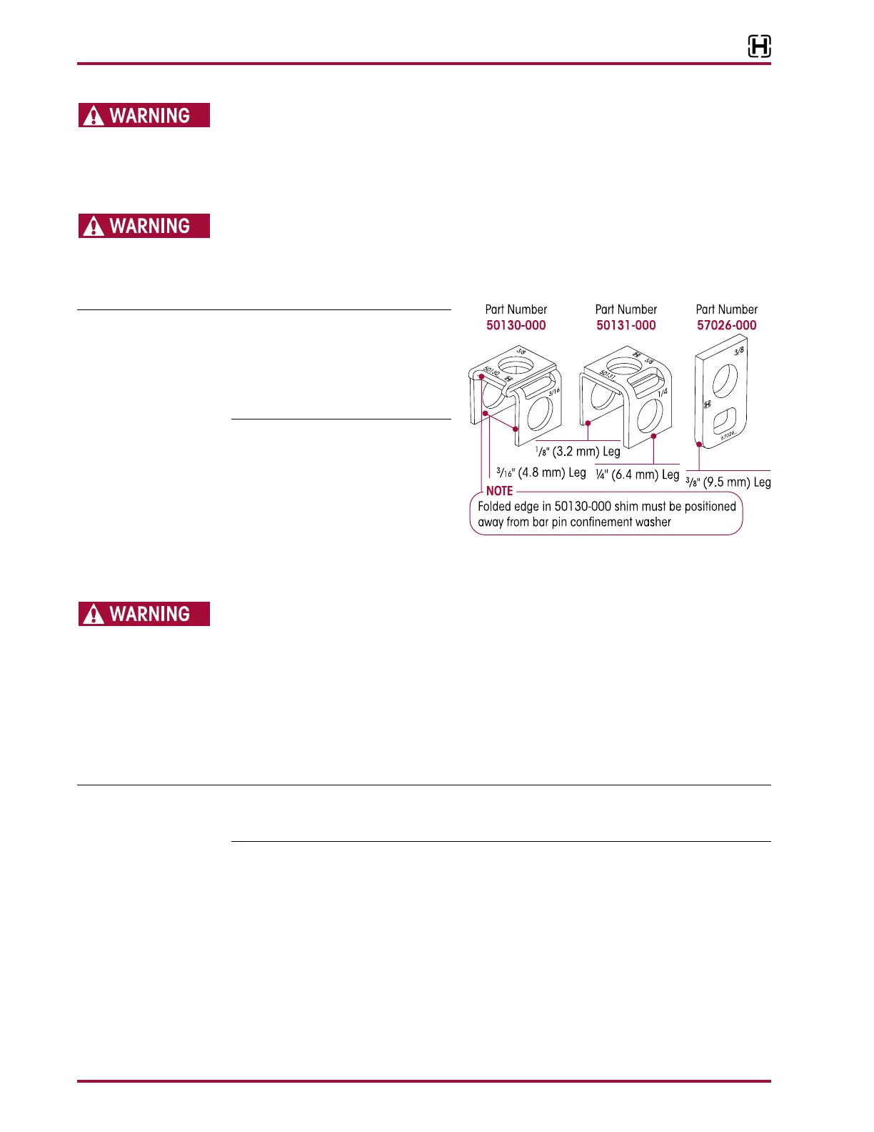
THE BAR PIN ALIGNMENT SHIM (PART NO. 50130-000) MUST BE INSTALLED WITH THE FOLDED EDGE
FACING AWAY FROM THE BUSHING, SEE FIGURE 8-13. FAILURE TO DO SO MAY RESULT IN SHIM DAMAGE,
IMPROPER ALIGNMENT, DAMAGE OR FRACTURE OF THE AXLE BRACKET OR BAR PIN WHICH COULD RESULT
IN THE ADVERSE VEHICLE HANDLING AND POSSIBLE PERSONAL INJURY OR PROPERTY DAMAGE.
Hendrickson recommends the use of
Grade 8 bolts and Grade C locknuts. If
flange head bolts and locknuts are not
used then hardened structural wash-
ers must be used under bolt heads
and locknuts.
8. Partially install the
bar pin alignment shim and verify
that the shim is in the same orien-
tation as prior to disassembly, see
Figure 8-10.
9. To complete installation of the
alignment shim, remove the tem-
porary ¾" bolt from the inboard bar pin hole and complete installation of the inboard
alignment shim.
DISCARD USED FASTENERS. ALWAYS USE NEW FASTENERS TO COMPLETE A REPAIR. FAILURE TO DO SO
COULD RESULT IN FAILURE OF THE PART OR MATING PARTS, ADVERSE VEHICLE HANDLING, PERSONAL
INJURY, OR PROPERTY DAMAGE.
10. Install the new 1" inboard bar pin fasteners. tighten at this time.
11. Repeat Steps 8 through 10 for the alignment shim.
12. Chock the drive axle wheels to prevent movement while installing the rear bar pin into
the axle bracket.
13. Support the current axle position of the rear axle pinion with a jack to assist with the installa-
tion of the rear bar pin.
Prior to disassembly of the longitudinal torque rod, note the quantity and orientation of the longitu-
dinal torque rod shims. It is required that the longitudinal torque rod shims are installed in the same
orientation and location as removed to preserve the existing pinion angle.
14. Disconnect the longitudinal torque rod from the axle bracket, see vehicle manu-
facturer’s specifications.
15. Release the rear parking brakes, this will allow the rear axle to rotate without rotating the tires.
16. Lower the rear drive pinion until the rear drive axle bracket legs are parallel to the rear bar pin
flats, see Figure 8-12.
17. Mount the equalizing beam into the drive axle brackets. install the bar pin
alignment shims at this time.
18. Slide a ¾" bolt through all rear axle bracket and the bar pin holes to temporarily support
the beams.