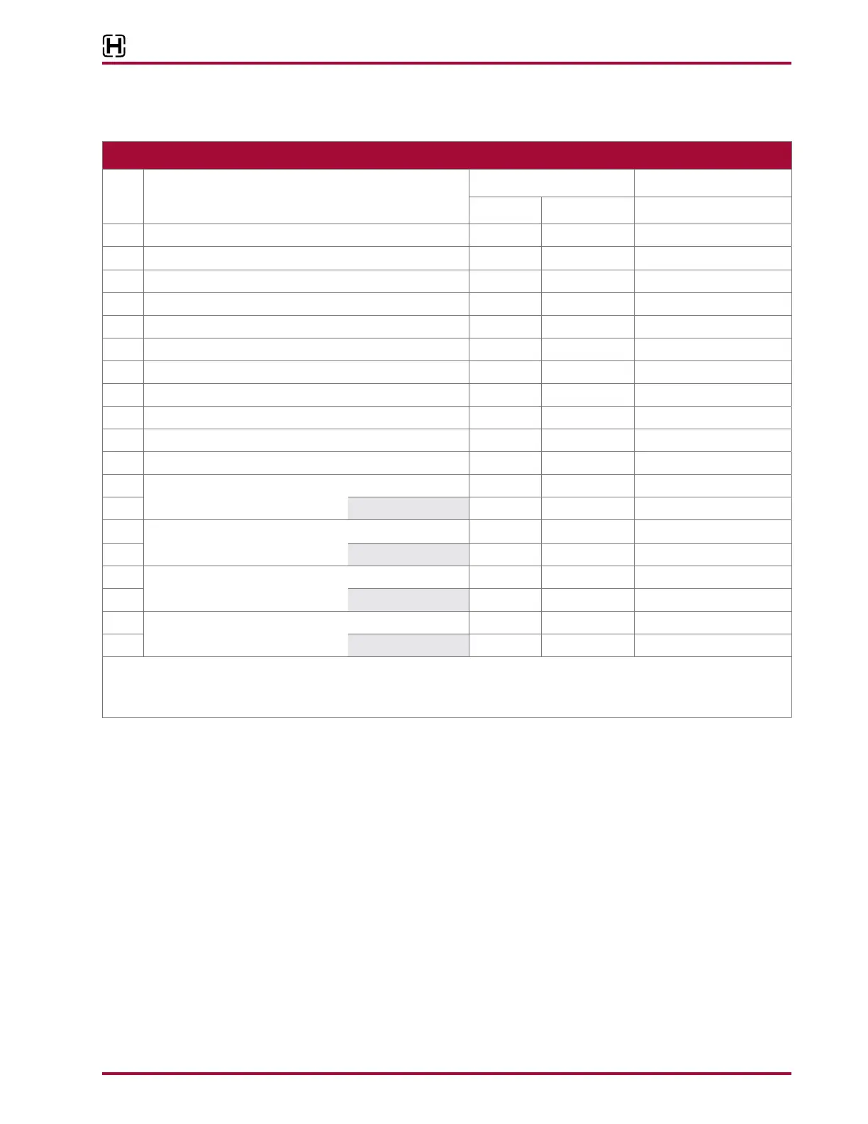
17730-241 71 Torque Specications
AR2
™
46K
1
Trailing Arm Assembly to Saddle Cap 8
7
⁄8"-14 UNF 250 ± 25
2
Trailing Arm Adapter 2 1"-14 UNS 470 ± 25
3
Upper Shock Locknut 2 ¾"-10 UNC 60 ± 10
4
Lower Shock Locknut 2 ¾"-10 UNC 60 ± 10
5
Air Spring Upper Locknut 4 ¾"-16 UNF 60 ± 10
6
Air Spring Lower Locknut 8 ½"-13 UNC 25 ± 5
7
Height Control Valve to Height Control Valve Bracket 4 ¼" -20 UNC 9 ± 1
8
Height Control Valve to Height Control Valve Linkage 4
5
⁄16"-18 UNC 11 ± 1
9
Height Control Valve Jam Nut 4
5
⁄16"-18 UNC 11 ± 1
10
Height Control Valve Linkage Clamp 2 Until Securely Fastened
11
Height Control Valve Bracket to Frame 4 ½"-13 UNC 60 ± 10
12A
Bar Pin Bushing
at the Locknut 8 1"-8 UNC 525 ± 75
12B
at the Bolt Head 8 1"-8 UNC 575 ± 75
13A
Bar Pin Bushing Adapter Style
AR2 46K 4 1"-16 UNF 470 ± 25
13B
AR2 40K 4 ¾"-16 UNF 225 ± 15
14A
Transverse Torque Rod to Axle Bracket
at the Locknut 2 1¼"-12 UNF 200 ± 25
14B
at the Bolt Head 2
5
⁄8"-11 UNC 75 ± 15
15A
Torque Rod to Frame
at the Locknut 4
5
⁄8"-11 UNC 185 ± 25
15B
at the Bolt Head 4
5
⁄8"-11 UNC 200 ± 25
Axle and frame mount hardware are supplied by vehicle manufacturer.
* Torque values listed above apply only if Hendrickson supplied fasteners are used. If non Hendrickson fasteners are used, follow
torque specications listed in the vehicle manufacturer’s service manual.