Mobile Rope Measurement MSM 12
Henning GmbH Page 9 2.0 / 3.2009
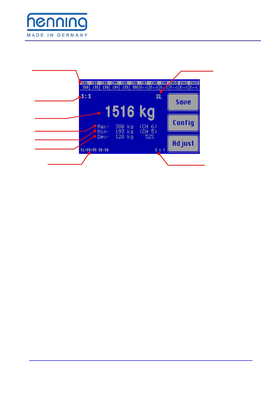
Figure 1: Main display
Die The individual weight display shows the measured load of each connected
rope load sensor. If no sensor is connected to the relevant measuring channel or if
the relevant rope load sensor is defective, Err1 is displayed. If the connected rope
load sensor is overloaded, Err2 is displayed.
The suspension ratio of the elevator can be selected by the user. The displayed
total weight is calculated by this factor. The individual weight display hereby remains
unaffected.
The total weight is the sum of all individual rope loads measured, if necessary con-
verted according to the suspension ratio. The output can be selected in different
weight units (kilogram (tons) or English pounds (short tons or long tons).
The maximum individual rope load display shows the actual load and the measur-
ing channel number of the sensor which is loaded with the highest weight in the rope
set. The minimum individual rope load display shows the corresponding informa-
tion for the rope with the lowest load.
The maximum deviation shows the absolute and percentage deviation of the rope
with the greatest deviation from the mean value of all ropes. The example in figure 1
shows a total weight of 1,516 kg distributed among 6 ropes. This means that under
ideal conditions each rope should carry 252 kg. However, the rope at measuring
channel 6 carries 380 kg, i. e. 128 kg corresponding to 52 % more load. (rounding
errors are possible)
If the mobile rope load meter LSM-XL is used (diameter range 16 – 24 mm) the rope
load meter must be switched over to this sensor type. The sensor type selected
(XL) appears on the display. When using LSM1 and LSM2 sensors this switching is
not required. In this case the display, where otherwise XL is indicated, remains blank.
type
Individual weight
display
sion ratio
Max. single load