


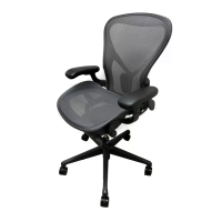
Do you have a question about the HermanMiller Aeron and is the answer not in the manual?
Remove four back bolts using a 5mm Hex bit.
Detach the chair back from the main assembly.
Remove the bolt securing the right swing arm.
Note: The right arm has right-hand thread direction.
Remove the left arm following previous steps; it has reverse threads.
Remove the nut and shoulder bolt.
Utilize a T27 Torx driver and a 10 mm wrench.
Remove the right side nut and shoulder bolt using prior methods.
Use a 6 mm drill bit to remove the swing arm bolt.
Repeat the previous step to remove the bolt on the opposite side.
Separate the seat from the swing arm assembly.
Release four snaps to remove the lower cover.
Squeeze the indicated snaps to detach the cover.
Remove the lower cover from the tilt assembly.
Remove the back cover from the chair.
Remove the front cover from the chair.
Detach the director component from the tilt housing.
Release the two indicated snaps.
Lift the director component out of the tilt housing.
Release the snap to lift the cable upwards.
Lift the cable to detach it from the actuator.
Slide the cable out to disconnect it from the actuator.
Remove the handle from the swing arm.
Lift the lever upwards.
Release the bottom snap mechanism.
Release the bracket from its socket.
Rotate the assembly and remove it from the swing arm.
Detach both swing arms from the chair assembly.
Pull the swing arms out of the assembly.
Turn the knob counter-clockwise to release tension.
Use a screwdriver to release the knob.
Remove the knob from the assembly.
Use a screwdriver to release the knob.
Remove the knob from the assembly.
Pull back the swing arm to release the forward limit.
Lift the tab while holding the swing arm to disengage the forward limit.
Rotate the casing to remove the leaf spring.
Remove the leaf spring from the assembly.
Use a T40 Torx bit to remove the pivot pin.
Remove the second pivot pin joint using the previous method.
Remove the bushing component.
Detach the tilt casting from the main assembly.
Use a hammer and punch to tap out the bushing, removing the B-Link.
Remove the right side bushing following the previous step.
Separate the B-Link from the assembly.
Use a T25 Torx bit to remove the cassette bolts.
Detach the tilt cassette after removing all cassette bolts.
Use a punch and hammer to remove the tilt housing.
Use a nylon cap and hammer to remove the cylinder from the base.
Pull off the castors to disassemble them from the base.
| Chair Type | Office Chair |
|---|---|
| Weight Capacity | 350 lbs |
| Warranty | 12-year warranty |
| Material | Pellicle Mesh |
| Adjustable Features | Armrests, Seat Height |
| Available Sizes | A, B, C |
| Base Material | Aluminum |
| Frame | Graphite, Polished Aluminum |
| Weight | 41 lbs |
| Color Options | Graphite, Mineral, Carbon |

 Loading...