Cylinder head
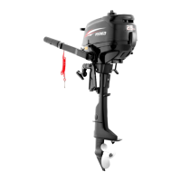
5. Check that the mark a on the cr
ankshaft
l is aligned with the hole b on the
camshaft m.
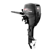
6. Install the push rods n and rocker arms
o, and then screw in the rocker arm
pivots p and valve adjusting locknuts q.
7. Install the crankcase. See “Installing the
crankcase”
8. Adjust the valve clearance. See steps 2
and 3 in “Adjusting the valve
clearance”.
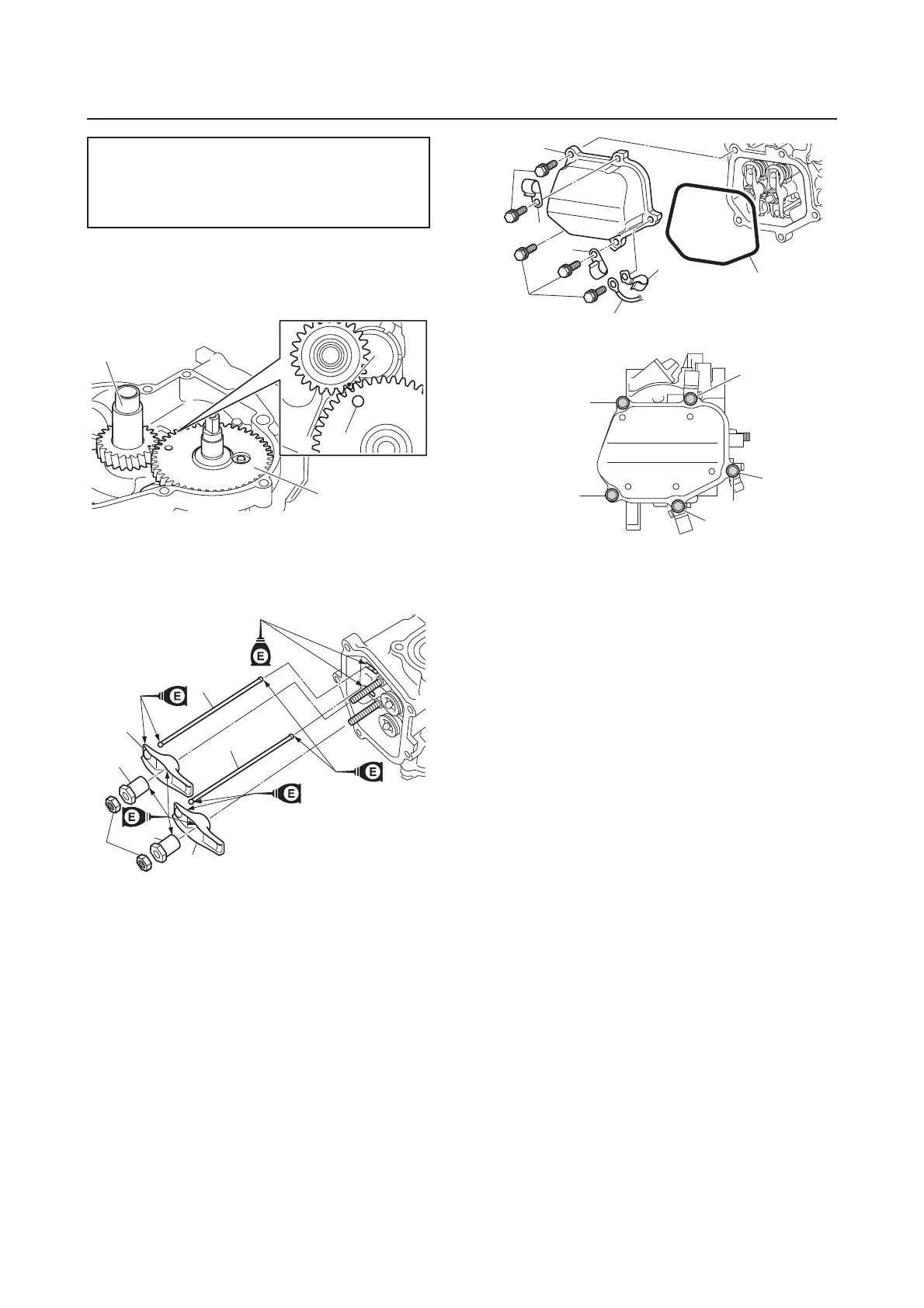
9. Install a new gasket r, the cylinder head
cover s, and the clamps t, u, and then
connect the ground lead j.
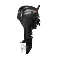
10. Tighten the bolts v in the order a, b,
and so on.
Thermostat cover anode screw g:
2 N·m (0.2 kgf·m, 1.5 ft·lb)
Spark plug k:
13 N·m (1.3 kgf·m, 9.6 ft·lb)
a
b
l
m
p
o
n
n
q
p
o
v
v
j
r
t
t
u
s
e
d
c
b
a
v
131