Chapter 2 System Wiring
The preparaon before installaon and general wiring.
Steps
1.
Draw a line based on the outer edge of the
le or right pedestal or column.
2.
Draw other parallel lines for installing the other pedestals.
Note
The distance between the nearest two line is 836 mm.
3.
Slot on the installaon surface and dig installaon holes according to the hole posion. Put 4
expansion bolts for each pedestal.
4.
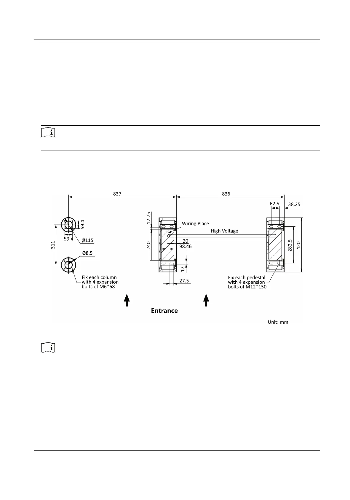
Bury cables. Each lane buries 1 high voltage cable. For details, see the system wiring diagram
below.
Figure 2-1 System Wiring Diagram
Note
●
High voltage: AC power input
●
The suggested inner diameter of the high voltage conduit is larger than 30 mm.
●
The external AC power cord should be double-insulated.
●
Before digging holes, evaluate the thickness of the
installaon surface to avoid puncturing.
●
The network cable must be CAT5e or the network cable has
beer performance.
●
If the usage scenarios of the equipment include kindergarten and primary school, it is
recommended to design dedicated turnsles for young children and lower grade students to
reduce the safety risks.
DS-K3G200(L)X Series Tripod Turnsle
3
 Loading...