Do you have a question about the Hilti DSF 1030-TS and is the answer not in the manual?
This document provides the original operating instructions for the Hilti DSF 1030-TS floor saw trolley, designed for professional use in cutting asphalt, concrete, and other mineral materials. It emphasizes safe and trouble-free handling, requiring users to read the documentation, observe safety instructions, and keep the instructions with the product.
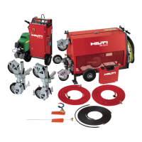
The DSF 1030-TS is a trolley specifically designed to mount a Hilti DST 10-CA or DST 10-E electric wall saw and its corresponding remote control unit, transforming the wall saw into a floor saw. This setup allows for controlled and precise cutting of various mineral materials. The floor saw trolley incorporates gear wheels that mesh with the saw head's advance motion drive. This advance motion is then transferred to the rear wheels of the trolley via a chain and a freewheel clutch.
The traction drive, which controls the saw's advance motion, can be engaged or disengaged using a foot-operated freewheel lever. When the freewheel clutch is engaged (lever in the right-hand position), the advance motion of the floor saw can be regulated by the remote control unit, allowing for automated cutting. When the freewheel clutch is disengaged (lever in the left-hand position), the floor saw trolley can be pushed manually, offering flexibility for positioning or non-powered movement.
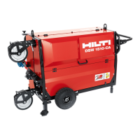
The system utilizes tap water as a dust-binding agent and for cooling both the saw blade and the motor, ensuring efficient and safer operation. A water supply system, including a water flow regulating valve, is integrated and must be mounted on the blade guard.
Before initial operation, several preparations are necessary. The handlebar of the trolley can be folded out and adjusted to the operator's height for comfortable steering. A cutting line indicator, which helps guide the saw along a marked line, needs to be brought into its working position by pulling out a securing pin, aligning the pointer, and re-inserting the pin.
The saw head is typically mounted on the left-hand side of the floor saw trolley (from the operator's perspective, looking in the direction of travel). However, for situations with limited space, such as corner cuts, the saw head can be turned 180° and mounted on the right-hand side. If the saw head is repositioned, the cutting line indicator must also be moved to the opposite side to maintain accurate guidance.
To mount the saw head, the clamping levers must be in the "released" detent position. The saw head is then placed on its mount on the trolley, ensuring the guide rollers are correctly positioned, and then locked securely. It's crucial to check for any play in the saw head after mounting.
For operation, the remote control unit for the saw is switched on, and the water supply is activated, with the flow rate adjusted as desired. The operator positions themselves behind the handlebar, starts the saw, lowers the blade, and begins the guide cut to a depth of 3 to 5 cm. Subsequent cuts can increase the depth by 3 to 5 cm each time, up to the maximum cutting depth.
Cutting can be performed either manually or using the traction drive. For manual advance, the traction drive must be disengaged, and the operator pushes the trolley with both hands on the grips. For traction drive operation, the drive is engaged, and the remote control unit regulates the direction and speed of advance, with the cutting line indicator used to track the line. At the end of a cut, the saw blade is lifted, and the trolley is returned to the starting point for the next pass. After completing work, the saw is switched off, the supply cord unplugged, and the water supply closed.
If the floor saw trolley consistently pulls to one side during operation, requiring steering corrections, the cutting line indicator may need adjustment. This involves releasing a locknut, screwing the hollow bolt into or out of the sleeve, and then re-inserting and positioning the pointer.
Regular care and maintenance are essential for the product's longevity and safe operation. The product, especially the grips, should be kept dry, clean, and free from oil and grease. It is important to clean the entire equipment immediately after finishing work and before long breaks, preventing dirt and slurry from drying onto parts. The clutch should also be cleaned and regreased, and the drive chain regreased each time after cleaning the floor saw trolley. High-pressure water-jet systems should not be used for cleaning the trolley.
At regular intervals, several components of the floor saw must be checked for damage and proper function. These include the saw head housing, remote control unit, saw blade and mounting flange, EMERGENCY OFF button, cables, blade guard, mounting system, chain drive, grips, and cutting line indicator.
When transporting the floor saw trolley without the saw head and weights, it should be lifted by the frame. The freewheel lever should be in the "disengaged" position to allow the trolley to be pushed to the desired location. Before any assembly or disassembly, the floor saw trolley must always be positioned on a horizontal surface, as the drive wheels cannot be locked without the saw head installed, posing a risk of the trolley rolling away on a slope.
| Blade Diameter | 254 mm |
|---|---|
| Arbor Size | 25.4 mm |
| Max Cutting Depth | 90 mm |
| Weight | 5.5 kg |
| Frequency | 60 Hz |
| Cable Length | 4 m |