HI 800 101 HIMatrix Engineering Manual
5.4.2 Field Buses
5.4.2.1 Fundamentals of RS-485 Transfer Mode System
The protocols for Profibus-DP, Modbus and Interbus communicate via the RS-485 transfer
mode system. The following table shows an overview over the basic physical features of
RS-485 transfer mode system:
Scope Feature Comment
Network
topology
Linear bus, active bus
termination on both ends
Branch lines should be avoided
Medium Shielded twisted cable
Shielding can be not applied
dependent of the environment
conditions
Number of
Stations
32 stations in each
segment without repeater
With repeater expandable up to
126 stations
Connector 9-pole MIN-D connector
Table 12: Basic features of the RS-485 transfer mode system
5.4.2.2 PROFIBUS DP
According to IEC 61158 two bus lines are noted. Wire type A can be used for transfer rates
up to 12 Mbit/s. Wire type B is out-dated and should not be used.
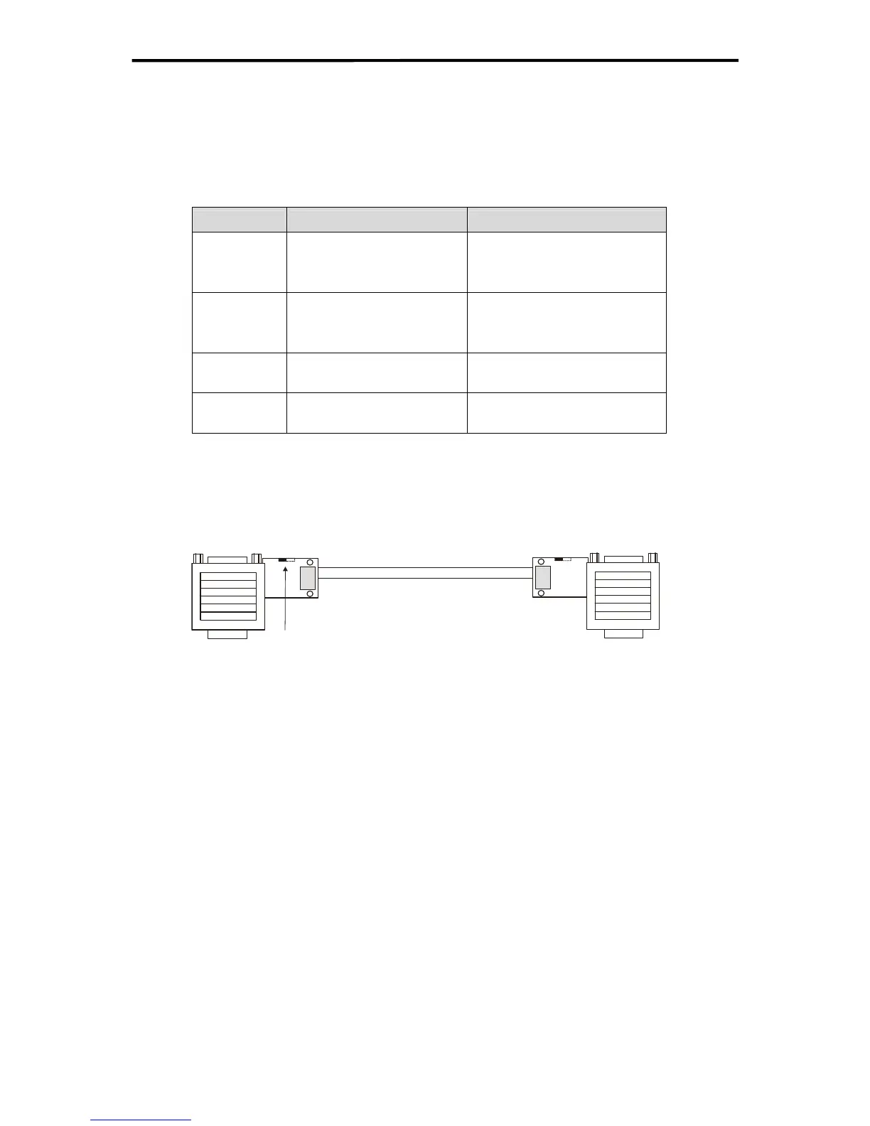
X1
MIN-D plug,
9-
ole
By selection of a switch the bus termination resistors
can be switched on at each end
X2
MIN-D plug,
9-pole
bus connector
Profibus cable type A
Figure 18: Wiring and bus termination for PROFIBUS-DP
As option to the shown 90º bus connectors, also straight and 45º offset connectors are avail-
able from HIMA.
Wiring and bus termination
The incoming and outgoing data cable is connected within the bus connector. Branch lines
are avoided and the connector can be plugged off from a controller without interruption of da-
ta line.
The PROFIBUS-DP bus termination has a resistor combination with which a defined zero
potential can be adjusted on the bus line. The resistor combination is integrated in the PRO-
FIBUS-DP bus connector and can be activated via bridges or switches. To guarantee an
even signal level the terminating resistors must be hooked up at the beginning and the end
of a segment.
Stations at the end of the bus should have a 5 V voltage at pin 6.
39 of 61
 Loading...


