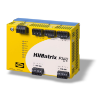
Do you have a question about the HIMA HIMatrix and is the answer not in the manual?
Describes the manual's organization, main chapters, and programming tool usage for HIMatrix remote I/Os.
Identifies the intended readers for this document, including system planners, configuration engineers, and programmers.
Explains the use of fonts for readability and the representation of safety notes and operating tips within the manual.
Details the structure and meaning of safety notes, including signal words like Warning, Caution, and Notice for risk prevention.
Explains how useful tips and tricks are presented in the manual for enhanced user guidance.
Defines the purpose of HIMatrix components in assembling safety-related controller systems.
Lists required environmental conditions for proper operation, including protection class, temperature, and altitude.
Outlines necessary precautions for handling electronic components to prevent damage from electrostatic discharge.
Discusses potential residual risks arising from engineering, user programs, or wiring faults in HIMatrix systems.
Emphasizes observing local safety requirements and using appropriate protective equipment on site.
Explains system behavior in emergencies and the importance of not impeding safe operation.
Describes how the remote I/O uses safety-related digital inputs and outputs for safe data transmission via safeethernet.
Details the connection and behavior of safety-related digital inputs, including LED indication and power supply options.
Explains system reaction to faults on digital inputs, including FAULT LED activation and error code handling.
Explains line control for detecting short-circuits/open-circuits on digital inputs, often used with EMERGENCY STOP buttons.
Details the connection and behavior of 2-pole digital outputs, including LED signaling and failure reactions.
Details system response to faults on digital outputs, including output de-energization and FAULT LED.
Details the line diagnosis feature for digital outputs, detecting short-circuits and open-circuits in 2-pole configurations.
Configuration for line diagnosis of lamp and inductive loads using short-circuit and open-circuit detection methods.
Explains line diagnosis for ohmic/capacitive loads using a reduced voltage test pulse for accurate detection.
Covers configuration of test period and monitoring time parameters influencing the line diagnosis feature.
Lists the available remote I/O variants and details the scope of delivery for the F3 DIO 16/8 01.
Explains how to note and affix the IP address and System ID on a label for device identification.
Describes the information found on the device's type plate, including product name, part number, and certifications.
Describes the physical layout, functional blocks, and communication aspects of the remote I/Os via safeethernet.
Classifies and describes the function of various LEDs on the remote I/O for indicating operating states.
Describes communication via safeethernet, including Ethernet interface properties and network ports.
Explains the use of digital pulsed outputs for detecting short-circuits and open-circuits on digital inputs.
Describes the function of the reset key for restoring default parameters and accounts when administrator access is unknown.
Provides general technical data for the F3 DIO 16/8 01, including response time, voltage, current, and dimensions.
Details specific product data for the F3 DIO 16/8 014 variant, including operating temperature and output current.
Lists the certifications and standards the HIMatrix F3 DIO 16/8 01 complies with, including SIL and PL ratings.
Describes how to mount the remote I/O on a DIN rail and take measures for proper cable laying and electrical properties.
Provides terminal assignments and functions for the 16 digital inputs of the F3 DIO 16/8 01.
Explains surge pulses on digital inputs and measures for ensuring proper operation in environments where surges may occur.
Details the terminal assignments and functions for the 8 2-pole digital outputs of the F3 DIO 16/8 01.
Specifies permitted configuration variants for digital outputs, including 1-pole, 2-pole, and 3-pole connections.
Provides the terminal assignments for the two pulsed outputs (TO 1 and TO 2) of the F3 DIO 16/8 01.
Details specifications for power supply and field zone cable plugs, including wire cross-section and tightening torque.
Describes requirements and special conditions for mounting the F3 DIO 16/8 01 in Zone 2 according to ATEX directives.
Introduces the configuration process using SILworX or ELOP II Factory programming tools.
Details configuring the remote I/O using SILworX, including module representation and parameter assignment.
Details configuring the remote I/O using ELOP II Factory, covering input/output assignment and system signals.
Describes how to configure line diagnosis for different load types (lamp, inductive, ohmic, capacitive).
Describes the proper wiring of the device for safety-related applications.
States that no specific handling of the remote I/O is required during operation.
Describes how to diagnose the remote I/O by evaluating LEDs and checking diagnostic entries in the controller.
Refers to sections detailing fault reactions for digital inputs/outputs and the STOP_INVALID state upon critical faults.
Outlines required maintenance measures, including loading operating system updates and executing proof tests.
| Model | HIMatrix |
|---|---|
| Product Type | Safety Controller |
| SIL Level | SIL 3 |
| Safety Integrity Level | SIL 3 |
| Input Voltage | 24 V DC (typically) |
| Power Supply | Redundant power supply option |
| Communication Protocols | PROFIBUS DP, PROFINET, Modbus TCP |
| Communication Interfaces | Ethernet, RS-485 |
| Operating Temperature | -40°C to +70°C |
| Dimensions | Varies depending on the specific module |
| Programming Languages | FBD (Function Block Diagram), LD (Ladder Diagram) |
