F3 DIO 16/8 01 4 Start-up
HI 800 177 E Rev. 2.00 Page 39 of 60
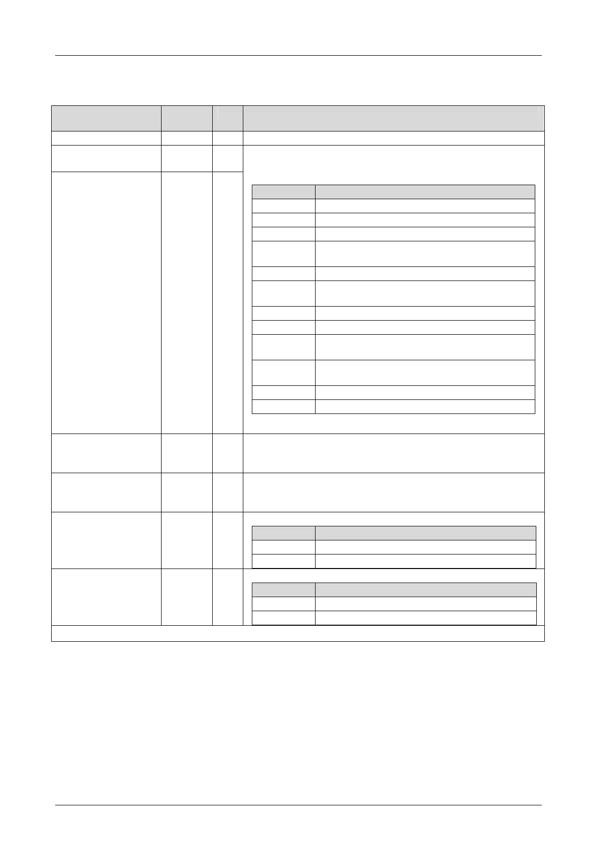
4.3.3.2 Tab: DO 8 03: Channels
The DO 8 03: Channels tab contains the following system parameters.
System parameter
Data
type
R/W Description
Channel no. --- R Channel number, defined by default
-> + Error Code
[WORD]
WORD R
-> - Error Code
[WORD]
WORD R
Error codes for the digital output channels DO+
Error codes for the digital output channels DO-
Coding Description
0x0001 Fault in the digital output module
0x0002 Channel shutdown due to overload
0x0004 Error while reading back the digital outputs
0x0008
Error while reading back the status of the
digital outputs
0x0010 Short-circuit
0x0020
Channel is switched off due to fault on the
corresponding channel
0x0040 Z-diode are destroyed at the output
0x0080 Open-circuit
0x0100
Test of the output switches provides in DO+
line causes an error
0x0200
Test of the output switches provides in DO-
line causes an error
0x0400 Test of the test switches L- causes an error
0x0800 External supply L+ at DO+
+ Value [BOOL] -> BOOL W Output value for DO+ channels, 1-pole (value: 0 or 1)
Output value for DO+ channels, 2-pole, identical to DO-
(Value: 0 or 1)
- Value [BOOL] -> BOOL W Output value for DO- channels, 1-pole (value: 0 or 1)
Output value for DO- channels, 2-pole, identical to DO+
(Value: 0 or 1)
2-pole [BOOL] -> BOOL W Configuration for a 2-Pole channel
Coding Description
FALSE Channel used for a 1-pole
TRUE Channel used for a 2-pole
Line Monitoring
[BOOL] ->
BOOL W Configuration of Line Diagnosis
Coding Description
FALSE LSLB
1)
diagnosis is not performed
TRUE LSLB
1)
diagnosis is performed
1)
SC/OC (SC = short-circuits, OC = open-circuits)
Table 27: SILworX - System Parameters for Digital Outputs, DO 8 03: Channels Tab