F3 DIO 16/8 01 4 Start-up
HI 800 177 E Rev. 2.00 Page 47 of 60
4.6 Connection Variants
This chapter describes the proper wiring of device in safety-related applications.
4.6.1 1-Pole Connection
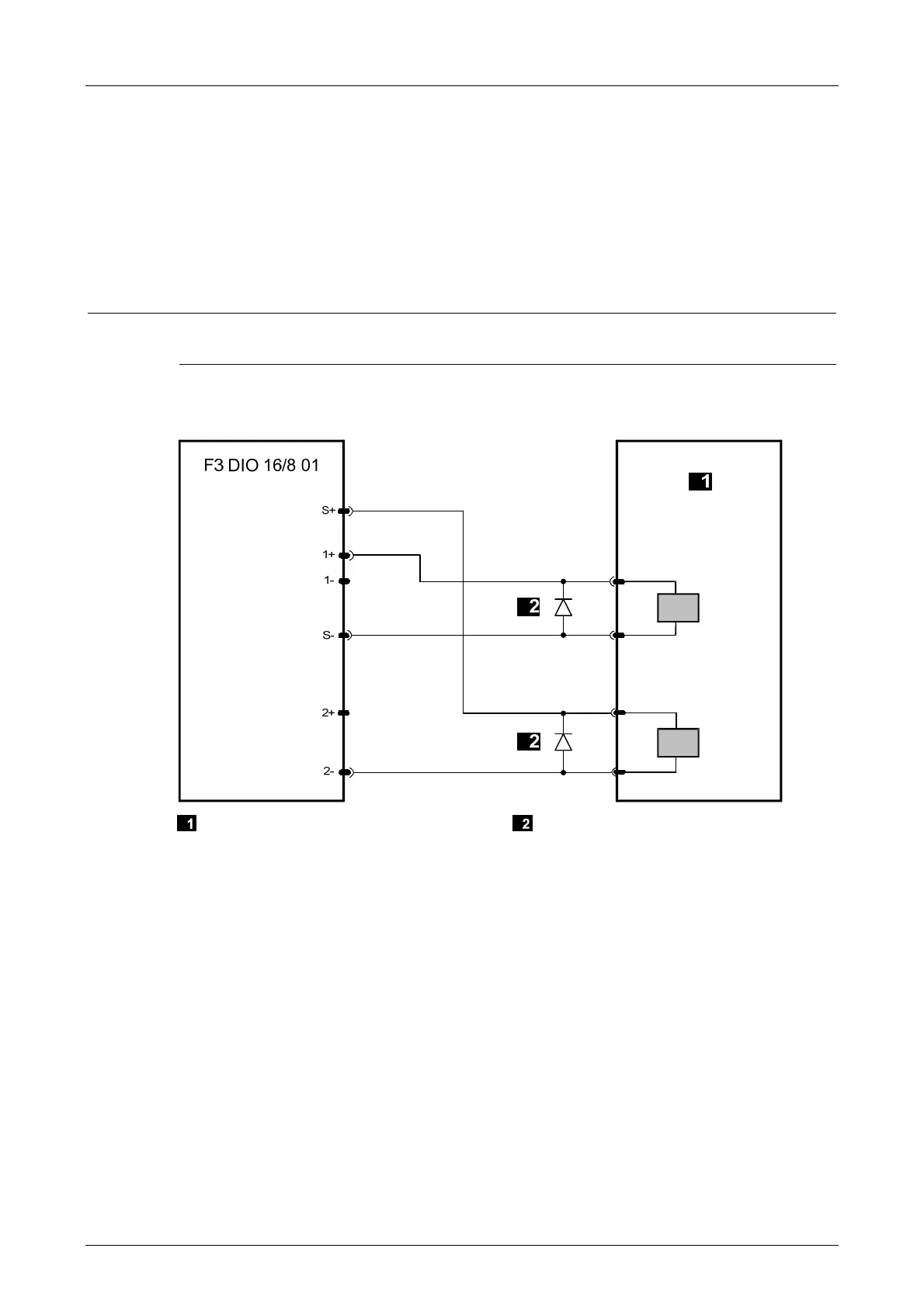
For 1-pole applications, the outputs DO+ must be connected to supply S- (load on S-) and the
outputs DO- must be connected to the supply S+ (load on S+).
In this case, 8 outputs DO+ and 8 outputs DO- are available.
No line diagnosis is possible for 1-pole applications.
i
A direct connection of the DO+ output to the external L- via the load or a connection of DO-
output to external L- via the load is not permitted!
Inductive loads may be connected with no free-wheeling diode on the actuator. However, HIMA
strongly recommends connecting a protective diode directly to the actuator.
Actuator Free-Wheeling Diode
Figure 11: 1-Pole Connection of an Actuator to the DO+ or DO- Output