F3 DIO 16/8 01 4 Start-up
HI 800 177 E Rev. 2.00 Page 29 of 60
4 Start-up
To start up the remote I/O, it must be mounted, connected and configured in the programming
tool.
4.1 Installation and Mounting
The remote I/O is mounted on a 35 mm DIN rail such as described in the HIMatrix System
Manual for Compact Systems.
When laying cables (long cables, in particular), take appropriate measures to avoid interference,
e.g., by separating the signal lines from the power lines.
When dimensioning the cables, ensure that their electrical properties have no negative impact
on the measuring circuit.
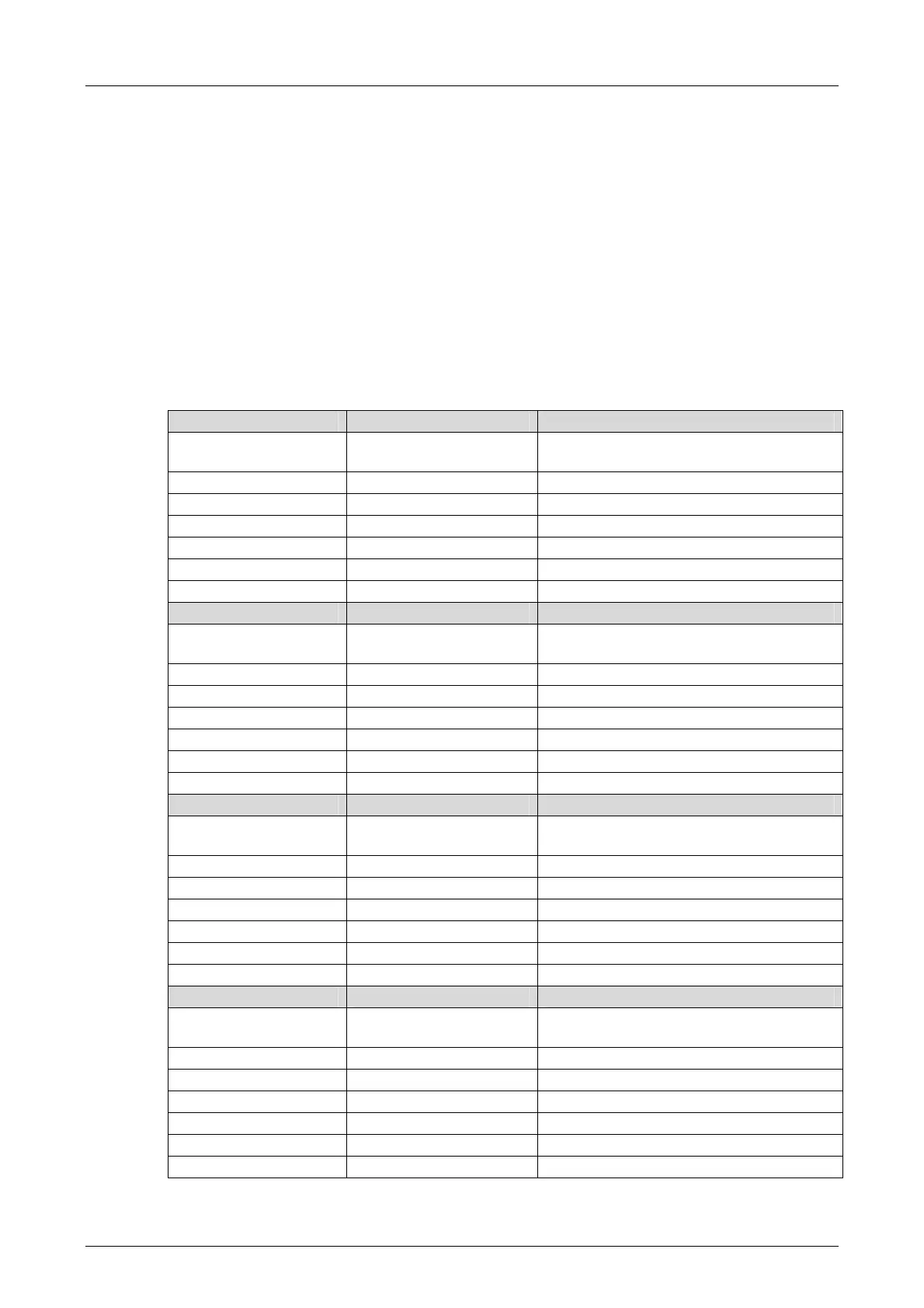
4.1.1 Installation and Terminals of the Digital Inputs
Terminal Designation Function
33, 34 LS+
Sensor supply for inputs 1...4,
buffered/unbuffered supply.
35 1 Digital input 1
36 2 Digital input 2
37 3 Digital input 3
38 4 Digital input 4
39, 40 L- Ground
41, 42 PA Shielding
Terminal Designation Function
43, 44 LS+
Sensor supply for inputs 5...8,
buffered/unbuffered supply.
45 5 Digital input 5
46 6 Digital input 6
47 7 Digital input 7
48 8 Digital input 8
49, 50 L- Ground
51, 52 PA Shielding
Terminal Designation Function
53, 54 LS+
Sensor supply for inputs 9...12,
buffered/unbuffered supply.
55 9 Digital input 9
56 10 Digital input 10
57 11 Digital input 11
58 12 Digital input 12
59, 60 L- Ground
61, 62 PA Shielding
Terminal Designation Function
63, 64 LS+
Sensor supply for inputs 13...16,
buffered/unbuffered supply.
65 13 Digital input 13
66 14 Digital input 14
67 15 Digital input 15
68 16 Digital input 16
69, 70 L- Ground
71, 72 PA Shielding
Table 18: Terminal Assignment for the Digital Inputs