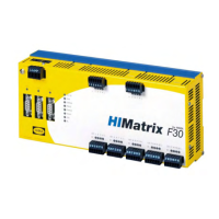
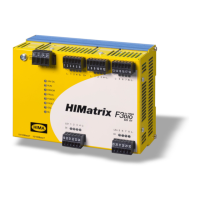
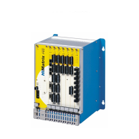
Do you have a question about the HIMA HIMatrix F30 03 and is the answer not in the manual?
Explains manual organization and lists other relevant documents.
Defines intended readers requiring specialized safety automation knowledge.
Details fonts, symbols, and conventions used in the document for readability.
Explains signal words (Danger, Warning, Caution) and structure of safety notes.
Defines HIMatrix components' purpose in safety-related controller systems.
Lists environmental conditions like temperature, pollution, and voltage for operation.
Provides guidance to prevent damage from electrostatic discharge during handling.
Identifies potential risks arising from engineering, user programs, or wiring faults.
Emphasizes adhering to local safety rules and using required protective equipment.
Explains system safe state during failure and emergency operational restrictions.
States the controller is equipped with safety-related digital inputs and outputs.
Details the 20 digital inputs, their LED status indication, and connection methods.
Explains how digital input faults are handled, including FAULT LED and error codes.
Details the 8 digital outputs, their LED status, and current load capacities.
Explains handling of digital output faults and FAULT LED activation.
Lists available components, their part numbers, and the programming tool.
Describes information on the device's type plate, including product name and conformity marks.
Covers the controller's layout, function, and communication connections.
Explains how various LEDs indicate the controller's operating state.
Describes the meaning of system LEDs like RUN, ERR, PROG, FORCE, FAULT, OSL, BL.
Discusses the controller's communication capabilities, including safeethernet.
Details Ethernet connection properties like ports, transfer standards, and supported protocols.
Lists UDP and TCP ports used for Ethernet communication protocols and their functions.
Explains the function and use of the reset key for administrator access and its effect on parameters.
Provides general technical specifications like memory, response time, interfaces, and operating voltage.
Lists certifications and standards met by the HIMatrix F30, including TÜV and EMC.
Describes how the controller is mounted on a 35 mm DIN rail.
Provides terminal assignments and functions for connecting the 20 digital inputs.
Provides terminal assignments and functions for connecting the 8 digital outputs.
Describes monitoring global variables and configuring up to 4000 events.
Details configuring the controller using the SILworX hardware editor and modules.
Configuration parameters for the CPU module in SILworX.
Configuration of Ethernet switch parameters like speed and flow control.
Presentation of statuses and parameters for the digital input module (DI 20).
Presentation of statuses and parameters for the digital output module (DO 8).
States that handling of the controller during operation is not required.
Explains initial diagnosis via LEDs and diagnostic history via SILworX.
Refers to fault reactions and describes the STOP_INVALID state.
Outlines required measures like OS loading and proof tests for the processor module.
Details the process of loading a new operating system version into the devices.
Specifies periodic testing requirements for HIMatrix devices.
Provides definitions for technical terms and acronyms used in the manual.
Lists all figures referenced in the document with their corresponding page numbers.
Lists all tables referenced in the document with their corresponding page numbers.
Provides an alphabetical index of keywords and their page references.
| Category | Controller |
|---|---|
| SIL | SIL 3 |
| Supply voltage | 24 V DC |
| Number of I/O modules | Up to 16 |
| Performance Level (PL) | PLe |
| Type | Safety Controller |
| Number of Inputs | Depends on configuration |
| Number of Outputs | Depends on configuration |
| Communication Interfaces | Ethernet |
| Certifications | IEC 61508, ISO 13849 |
