3 Product Description F30 03
Page 18 of 46 HI 800 473 E Rev. 1.00
3.4.1.3 Communication LEDs
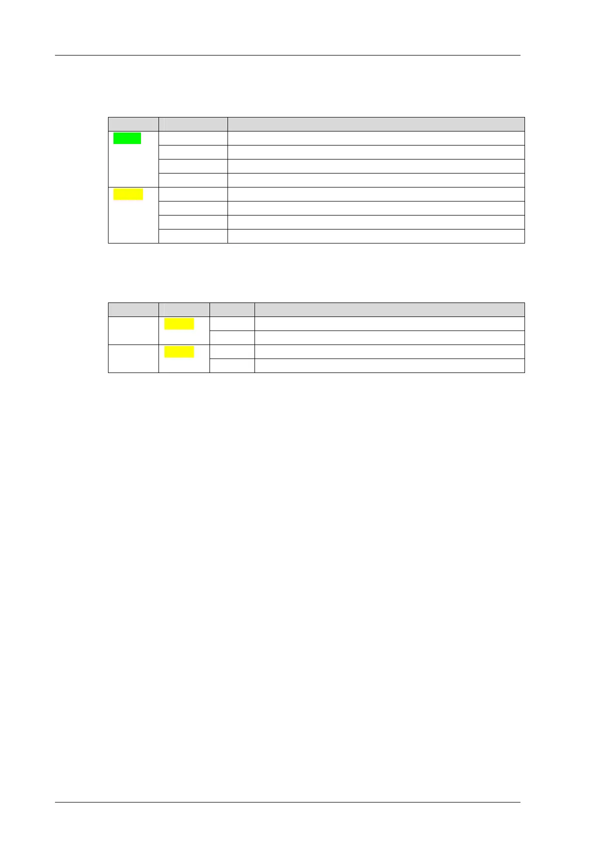
All RJ-45 connectors are provided with a small green and a yellow LEDs. The LEDs signal
the following states:
LED Status Description
On Full duplex operation
Blinking1 IP address conflict, all communication LEDs are blinking
Blinking-x Collision
Green
Off Half duplex operation, no collision
On Connection available
Blinking1 IP address conflict, all communication LEDs are blinking
Blinking-x Interface activity
Yellow
Off No connection available
Table 7: Ethernet Indicators
3.4.1.4 I/O LEDs
LED Color Status Description
On The related channel is active (energized). DI 1…20 Yellow
Off The related channel is inactive (de-energized).
On The related channel is active (energized). DO 1…8 Yellow
Off The related channel is inactive (de-energized).
Table 8: I/O LEDs
3.4.1.5 Fieldbus LEDs
LEDs FB1…FB3 are used to display the state of communication occurring via the serial
interfaces. The function of the LED depends on the used protocol.
Refer to the SILworX Communication Manual (HI 801 101 E) for more details on the
function.

 Loading...


