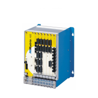
Do you have a question about the HIMA HIMatrix F2 DO 16 01 and is the answer not in the manual?
Outlines manual structure, chapters, and programming tool usage.
Identifies intended readers: planners, engineers, programmers, and authorized personnel.
Explains document formatting, font usage, and special note conventions.
States HIMatrix components are for safety-related controller systems.
Details protection class, temperature, pollution, altitude, housing, and voltage requirements.
Advises on protecting devices from electrostatic discharge during handling.
Discusses potential risks stemming from engineering, program, or wiring faults.
Emphasizes adherence to local safety rules and using required protective equipment.
Explains system behavior during faults and emergency situations.
Explains the remote I/O's role in safety-related outputs assigned by the controller.
Details the 16 digital outputs, their signaling, and current load limits.
Describes how outputs react to faults, overload, and communication loss.
Lists available remote I/O variants and their specifications.
Explains IP address and System ID configuration and default values.
Details the information found on the device's type plate.
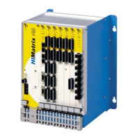
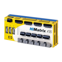
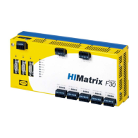
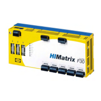
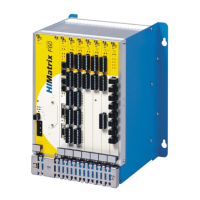
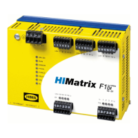
Describes the layout and function of remote I/Os and their communication.
Explains the function of various LEDs on the remote I/O.
Details the 24 VDC operating voltage LED status.
Explains the RUN, ERROR, PROG, FORCE, FAULT, OSL, BL LEDs.
Describes the Ethernet communication LEDs.
Explains the status of I/O LEDs for digital outputs.
Details the communication methods and interfaces.
Details Ethernet interface properties like ports, transfer standards, and protocols.
Lists UDP ports and their usage for communication.
Explains the function and usage of the device's reset key.
Provides general technical specifications and digital output details.
Lists product data specific to the F2 DO 16 014 variant for railway applications.
Lists certifications and standards met by the HIMatrix F2 DO 16 01.
Describes mounting the remote I/O on a DIN rail and cable considerations.
Provides terminal assignments for connecting digital outputs to the device.
Explains connecting the operating voltage to the device groups.
Details properties of power supply and field zone cable plugs.
Covers mounting requirements and special conditions for Zone 2 installation.
Explains configuration using SILworX or ELOP II Factory programming tools.
Details configuration steps using the SILworX programming tool.
Specifies system parameters and error codes for outputs in SILworX.
Presents statuses and parameters for the output module in SILworX.
Lists system parameters available in the SILworX Module tab.
Lists system parameters available in the SILworX DO 16: Channels tab.
Details configuration steps using the ELOP II Factory programming tool.
Explains assigning signals to individual channels using ELOP II Factory.
Specifies system signals and error codes for outputs in ELOP II Factory.
Lists system signals and error codes for digital outputs in ELOP II Factory.
States no specific handling is required during operation.
Mentions evaluating LEDs and using the programming tool for diagnosis.
Refers to fault reaction of digital outputs and module fault states.
Lists key maintenance tasks like loading OS and proof testing.
Details the process of updating the device's operating system.
Mentions proof testing requirements for HIMatrix devices.
| Series | HIMatrix |
|---|---|
| Function | Digital Output Module |
| Part Number | F2 DO 16 01 |
| Digital Outputs | 16 |
| Output Type | Solid State |
| Output Voltage Range | 24 V DC |
| Max Output Current per Channel | 0.5 A |
| Operating Voltage | 24 V DC |
| Safety Integrity Level | SIL 3 |
| Protection Class | IP20 |
| Redundancy | Supported |
| Product Type | Controller |
| Certification | IEC 61508 |
| Connection Type | Removable Terminal Block |
| Operating Temperature Range | -40°C to +70°C |
