4 Start-up F2 DO 16 01
Page 22 of 40 HI 800 159 E Rev. 2.00
4 Start-up
To start up the remote I/O, it must be mounted, connected and configured in the programming
tool.
4.1 Installation and Mounting
The remote I/O is mounted on a 35 mm DIN rail such as described in the HIMatrix system
manual for compact systems.
When laying cables (long cables, in particular), take appropriate measures to avoid interference,
e.g., by separating the signal lines from the power lines.
When dimensioning the cables, ensure that their electrical properties have no negative impact
on the measuring circuit.
4.1.1 Connecting the Digital Outputs
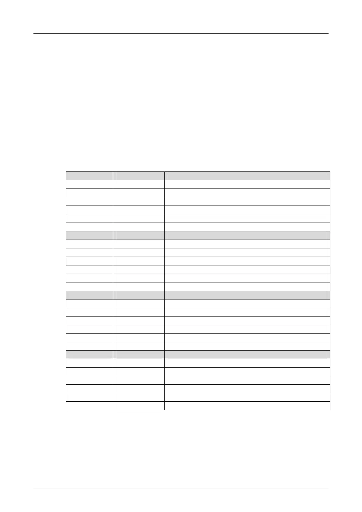
Use the following terminals to connect the digital outputs:
Terminal Designation Function (outputs D1, above)
1 L- Ground channel group D1
2 1 Digital output DO 1
3 2 Digital output DO 2
4 3 Digital output DO 3
5 4 Digital output DO 4
6 L- Ground channel group D1
Terminal Designation Function (outputs D1, below)
13 L- Ground channel group D1
14 9 Digital output DO 9
15 10 Digital output DO 10
16 11 Digital output DO 11
17 12 Digital output DO 12
18 L- Ground channel group D1
Terminal Designation Function (outputs D2, above)
7 L- Ground channel group D2
8 5 Digital output DO 5
9 6 Digital output DO 6
10 7 Digital output DO 7
11 8 Digital output DO 8
12 L- Ground channel group D2
Terminal Designation Function (outputs D2, below)
19 L- Ground channel group D2
20 13 Digital output DO 13
21 14 Digital output DO 14
22 15 Digital output DO 15
23 16 Digital output DO 16
24 L- Ground channel group D2
Table 15: Terminal Assignment for the Digital Outputs

 Loading...


