F2 DO 16 01 4 Start-up
HI 800 159 E Rev. 2.00 Page 23 of 40
4.1.2 Connecting the Operating Voltage
Each group includes 8 channels. The two groups are supplied individually with separate
operating voltages, however, both clamp terminal blocks must be connected.
A group's total current input must not exceed 9 A. If a group exceeds the total current input, it is
switched off and then switched on again cyclically.
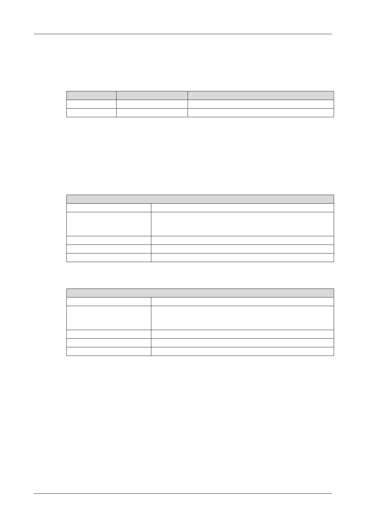
Group Clamp terminal block Output channels
D1 (left) L-, L-, L+1, L+1 1...4 and 9...12
D2 (right) L-, L-, L+2, L+2 5...8 and 13...16
Table 16: Connecting the Operating Voltage
4.1.3 Cable plugs
Cable plugs attached to the pin headers of the devices are used to connect to the power supply
and to the field zone. The cable plugs are included within the scope of delivery of the HIMatrix
devices and modules.
The devices power supply connections feature the following properties:
Connection to the power supply
Cable plugs 2 pieces, four poles, screw terminals
Wire cross-section 0.2…2.5 mm
2
(single-wire)
0.2…2.5 mm
2
(finely stranded)
0.2…2.5 mm
2
(with wire end ferrule)
Stripping length 10 mm
Screwdriver Slotted 0.6 x 3.5 mm
Tightening torque 0.4…0.5 Nm
Table 17: Power Supply Cable Plug Properties
Connection to the field zone
Number of cable plugs 4 pieces, six poles, screw terminals
Wire cross-section 0.2…1.5 mm
2
(single-wire)
0.2…1.5 mm
2
(finely stranded)
0.2…1.5 mm
2
(with wire end ferrule)
Stripping length 6 mm
Screwdriver Slotted 0.4 x 2.5 mm
Tightening torque 0.2…0.25 Nm
Table 18: Input and Output Cable Plug Properties

 Loading...


