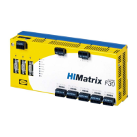
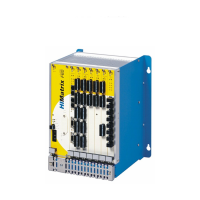
Do you have a question about the HIMA HIMatrix F35 and is the answer not in the manual?
Explains the manual's composition, chapter breakdown, and how to navigate its sections.
Identifies the intended readers, including system planners, engineers, and maintenance personnel.
Details font usage (bold, italics, courier) and notation for improved readability and usability.
Information on HIMA's training programs and contact for service department inquiries.
Describes the permissible conditions and applications for using HIMatrix systems safely.
Details crucial environmental parameters like protection class, temperature, pollution, and altitude.
Outlines the critical responsibilities for safe operation and programming validation by users.
Specifies essential measures for handling electronic components to prevent damage from electrostatic discharge.
Identifies potential sources of residual risk arising from engineering, user program, or wiring faults.
Emphasizes adherence to local safety regulations and the mandatory use of required protective equipment.
States system behavior during emergencies and prohibits actions that compromise safe operation.
Explains the functionality of line control for detecting short-circuits and open-circuits in circuits.
Details how to implement open-circuit and short-circuit monitoring specifically for digital inputs on the F35 model.
Specifies the required nominal and operational supply voltage limits and monitoring for system stability.
Describes temperature monitoring mechanisms and how system variables change based on detected temperature thresholds.
Explains the system's reaction to short-circuits, including channel behavior and potential shutdown.
Details the system's capability to record alarms and sequences of events with timestamps for analysis.
Lists key technical specifications such as power supply, operating temperature, and protection type.
Explains the process of activating features like multitasking and event recording using software licenses.
Lists and describes the various Ethernet and fieldbus communication protocols supported by HIMatrix controllers.
Covers Ethernet-based communication, including safeethernet, its configuration, and protocols.
Describes fieldbus communication options, required submodules, and controller compatibility.
Details the fundamental functions of the operating system and its interface with the user program.
Explains how to access and view the current COM and CPU operating system versions.
Categorizes and describes the system's behavior and reactions to permanent, temporary, and internal faults.
Describes the processor system's central role in communication and monitoring within the controller.
Outlines the allowed modes for user program execution: RUN, Test Mode, STOP, and ERROR.
Explains the CPU cycle sequence and the multitasking capability for executing multiple user programs.
Details the process and considerations for transferring modified programs during operation without stopping the controller.
Introduces the concept of forcing variables, its purposes, and associated warnings.
Explains forcing at global and local levels, including time limits and the Force Editor.
Covers forcing parameters, time limits, and automatic reset behavior for older CPU OS versions.
Discusses heat dissipation, its impact on system installation, and component lifetime based on enclosure design.
Covers guidelines for installing and mounting HIMatrix controllers, including DIN rail attachment and clearances.
Guides the configuration of system resources, parameters, and user management using SILworX.
Explains how to set up and manage user access schemes for projects and controllers to control access.
Describes configuring Ethernet interfaces and communication parameters using SILworX.
Details how to define and configure alarms and events, including Boolean and scalar event parameters.
Covers configuration options for resources, user programs, and I/O using ELOP II Factory.
Guides communication configuration, focusing on Ethernet interfaces and safeethernet using ELOP II Factory.
Explains system signals for reading safeethernet status and controlling communication parameters.
Details parameters for configuring safeethernet connections, including profiles, response time, and TMO.
Describes the process of configuring signals for safeethernet communication using drag-and-drop in ELOP II Factory.
Explains how to influence program function using the PADT, including setting parameters, switches, and modes.
Describes setting user program parameters and switches offline or online via the PADT.
Explains how to start the user program from a stopped state, including test mode and cold/warm starts.
Details the system's behavior and restart procedure when the program enters an invalid configuration state.
Describes the procedure for stopping the user program, transitioning from RUN to STOP.
Explains how to use program test mode for debugging, covering cold, warm, and hot start behaviors.
Describes using online test fields (OLT) to display and force signals/variables while the controller is active.
States that normal operation requires no direct handling, but intervention may be needed for problem resolution.
Explains how to perform initial diagnosis using LEDs and detailed analysis via diagnostic history.
Describes the function and meaning of LEDs that indicate controller operating states and system status.
Details the recorded states of processor and communication systems in short and long-term diagnosis logs.
Guides users on accessing the diagnostic panel within the SILworX Hardware Editor for detailed analysis.
Explains how to access the diagnostic panel using the ELOP II Factory Hardware Management interface.
Describes common disturbances in the processor system, indicated by the ERROR LED, and troubleshooting steps.
Covers the process of replacing processor and communication system operating systems if necessary.
Provides step-by-step instructions for loading operating systems using SILworX for relevant controllers.
Details the steps for loading operating systems using ELOP II Factory for controllers with older OS versions.
Compares programming tools and OS versions for switching between ELOP II Factory and SILworX on compatible controllers.
States that unauthorized repair is prohibited; defective units must be returned to HIMA for servicing.
| Supply Voltage | 24 V DC |
|---|---|
| Operating Temperature | -40 °C to +70 °C |
| Storage Temperature | -40°C to +85°C |
| SIL | SIL 3 |
| Safety Standard | IEC 61508 |
| Performance Level (PL) | PL e |
| CPU | 32-bit |
| Communication Interfaces | Ethernet, RS485 |
| Certifications | ATEX, IECEx |
