4 Start-up F2 DO 16 01
Page 24 of 40 HI 800 159 E Rev. 2.00
4.1.4 Mounting the F2 DO 16 01 in Zone 2
(EC Directive 94/9/EC, ATEX)
The remote I/O is suitable for mounting in zone 2. Refer to the corresponding declaration of
conformity available on the HIMA website.
When mounting the device, observe the special conditions specified in the following section.
Specific Conditions X
1. Mount the remote I/O in an enclosure that meets the EN 60079-15 requirements and
achieves a type of protection of at least IP54, in accordance with EN 60529. Provide the
device with the following label:
Work is only permitted in the de-energized state
Exception:
If a potentially explosive atmosphere has been precluded, work can be also performed when
the device is under voltage.
2. The enclosure in use must be able to safely dissipate the generated heat. Depending on the
output load and supply voltage, the HIMatrix F2 DO 16 01 module has a power dissipation
ranging between 9 W and 32 W.
3. Protect the HIMatrix F2 DO 16 01 with a 10 A time-lag fuse.
The 24 VDC power must come from a power supply unit with safe isolation. Use power
supply units of type PELV or SELV only.
4. Applicable standards:
VDE 0170/0171 Part 16, DIN EN 60079-15: 2004-5
VDE 0165 Part 1, DIN EN 60079-14: 1998-08
Pay particular attention to the following sections
DIN EN 60079-15:
Chapter 5 Design
Chapter 6 Terminals and cabling
Chapter 7 Air and creeping distances
Chapter 14 Connectors
DIN EN 60079-14:
Chapter 5.2.3 Equipment for use in zone 2
Chapter 9.3 Cabling for zones 1 and 2
Chapter 12.2 Equipment for zones 1 and 2
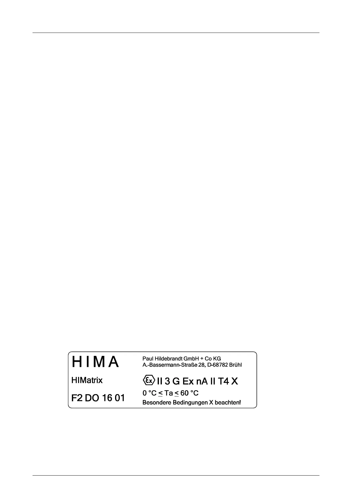
The remote I/O is additionally equipped with the label represented below:
Figure 6: Label for Ex Conditions

 Loading...


