3 Product Description F30 03
Page 12 of 46 HI 800 473 E Rev. 1.00
3.1.2 Safety-Related Digital Outputs
The controller is equipped with 8 digital outputs. The state (HIGH, LOW) of each output is
signaled by an individual LED (HIGH, LOW).
At the maximum ambient temperature, each of the outputs 1...3 and 5...7 can be loaded
with 0.5 A, and outputs 4 and 8 can be loaded with 1 A or 2 A at an ambient temperature of
up to 50 °C.
If an overload occurs, one or all digital outputs are switched off. If the overload is removed,
the outputs are switched on again automatically, see
Table 14.
The external wire of an output is not monitored, however, a detected short-circuit is
signaled.
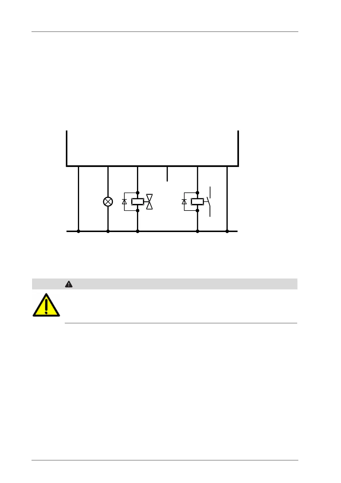
DO1
L-
DO2
DO3
DO4
L-
Figure 3: Connection of Actuators to Outputs
The redundant connection of two outputs must be decoupled with diodes.
WARNING
For connecting a load to a one-pole switching output, use the corresponding L-
ground of the respective channel group (two-pole connection) to ensure that the
internal protective circuit can function.
Inductive loads may be connected with no free-wheeling diode on the actuator. However,
HIMA strongly recommends connecting a protective diode directly to the actuator.

 Loading...


