F30 03 3 Product Description
HI 800 473 E Rev. 1.00 Page 11 of 46
3.1.1.1 Reaction in the Event of a Fault
If the device detects a fault on a digital input, the user program processes a low level in
accordance with the de-energized to trip principle.
The device activates the FAULT LED.
In addition to the channel signal value, the user program must also consider the
corresponding error code.
The error code allows the user to configure additional fault reactions in the user program.
3.1.1.2 Line Control
Line control is used to detect short-circuits or open-circuits and can be configured for the
F30 system, e.g., on EMERGENCY STOP inputs complying with Cat. 4 in accordance with
EN 954-1.
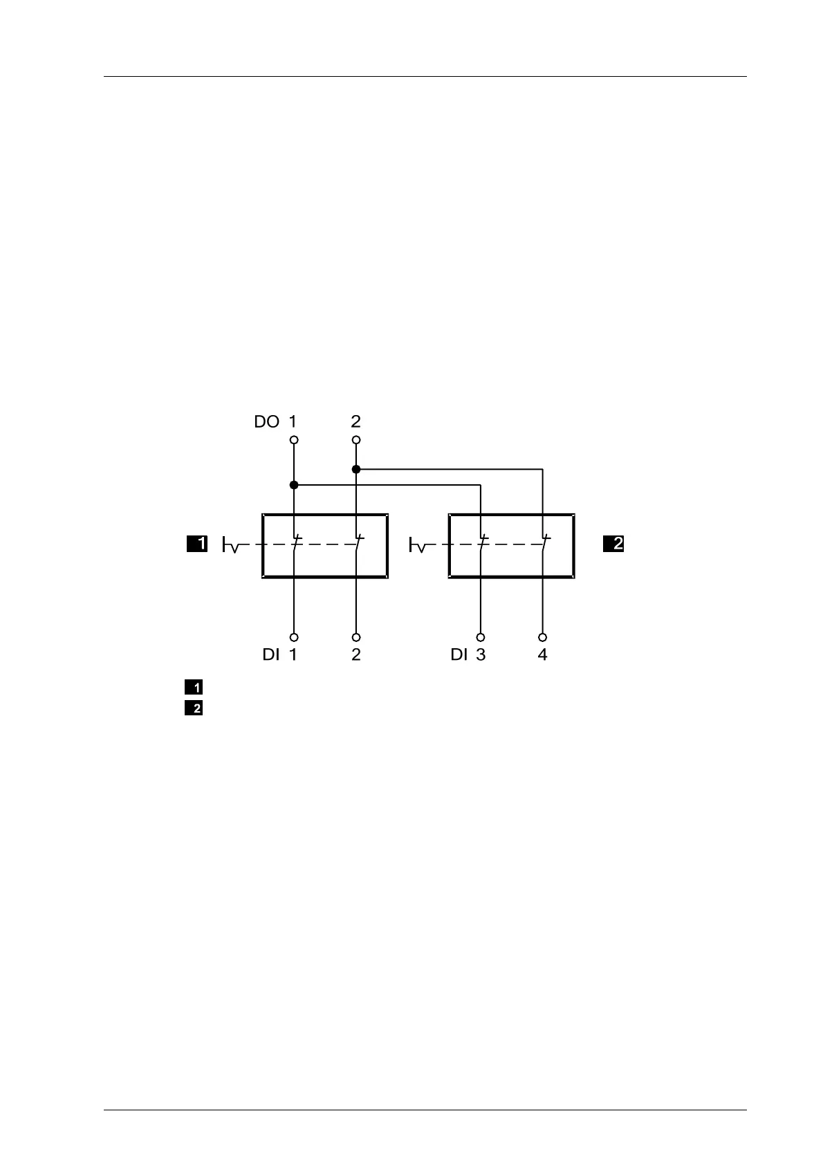
To this end, connect the digital outputs DO 1 through DO 8 of the system to the digital
inputs DI of the same system as follows:
EMERGENCY STOP 1
EMERGENCY STOP 2
EMERGENCY STOP devices in
accordance with EN 60947-5-1 and
EN 60947-5-5
Figure 2: Line Control
The controller pulses the digital outputs to detect the line short-circuits and open-circuits to
the digital inputs. To do so, configure the Value [BOOL] -> system variable in SILworX. The
variables for the pulsed outputs must begin with channel 1 and reside in direct sequence,
one after the other.
If the following faults occur, the FAULT LED located on the front plate of the controller
blinks, the inputs are set to low level and an (evaluable) error code is created:
Cross-circuit between two parallel wires.
Invalid connections of two lines (e.g., DO 2 to DI 3),
Earth fault on one wire (with earthed ground only).
Open-circuit or open contacts, i.e., including when one of the two EMERGENCY STOP
switches mentioned above has been engaged, the FAULT LED blinks and the error
code is created.
For more information on how to configure line control in the user program, refer to the
HIMatrix Engineering Manual (HI 800 101 E).

 Loading...


