F3 DIO 16/8 01 3 Product Description
HI 800 177 E Rev. 2.00 Page 13 of 60
3 Product Description
The safety-related F3 DIO 16/8 01 remote I/O is a compact system in a metal housing with
16 digital inputs, 8 2-pole digital outputs and 2 pulsed outputs. The 2-pole outputs consist of
2 switches connected in series, one switching to L+ and the other switching to L-.
The remote I/O is available in various model variants for SILworX and ELOP II Factory, see
Table 4.
Remote I/O
s are connected to individual HIMax or HIMatrix controllers via safeethernet. They
are used to extend the I/O level, but are not able to run any user program by themselves.
The remote I/O is suitable for mounting in Ex-zone 2, see Chapter 4.1.6.
The device is TÜV-certified
for safety-related applications up to SIL 3 (IEC 61508, IEC 61511
and IEC 62061), Cat. 4 and PL e (EN ISO 13849-1) and SIL 4 (EN 50126, EN 50128 and
EN 50129).
Further safety standards, application standards and test standards are specified in the
certificates available on the HIMA website.
3.1 Safety Function
The remote I/O is equipped with safety-related digital inputs and outputs. The input values on
the inputs are safely transmitted to the connected controller via safeethernet. The outputs are
safely assigned their values by the connected controller via safeethernet.
3.1.1 Safety-Related Digital Inputs
The state (HIGH, LOW) of each input is signaled by an individual LED.
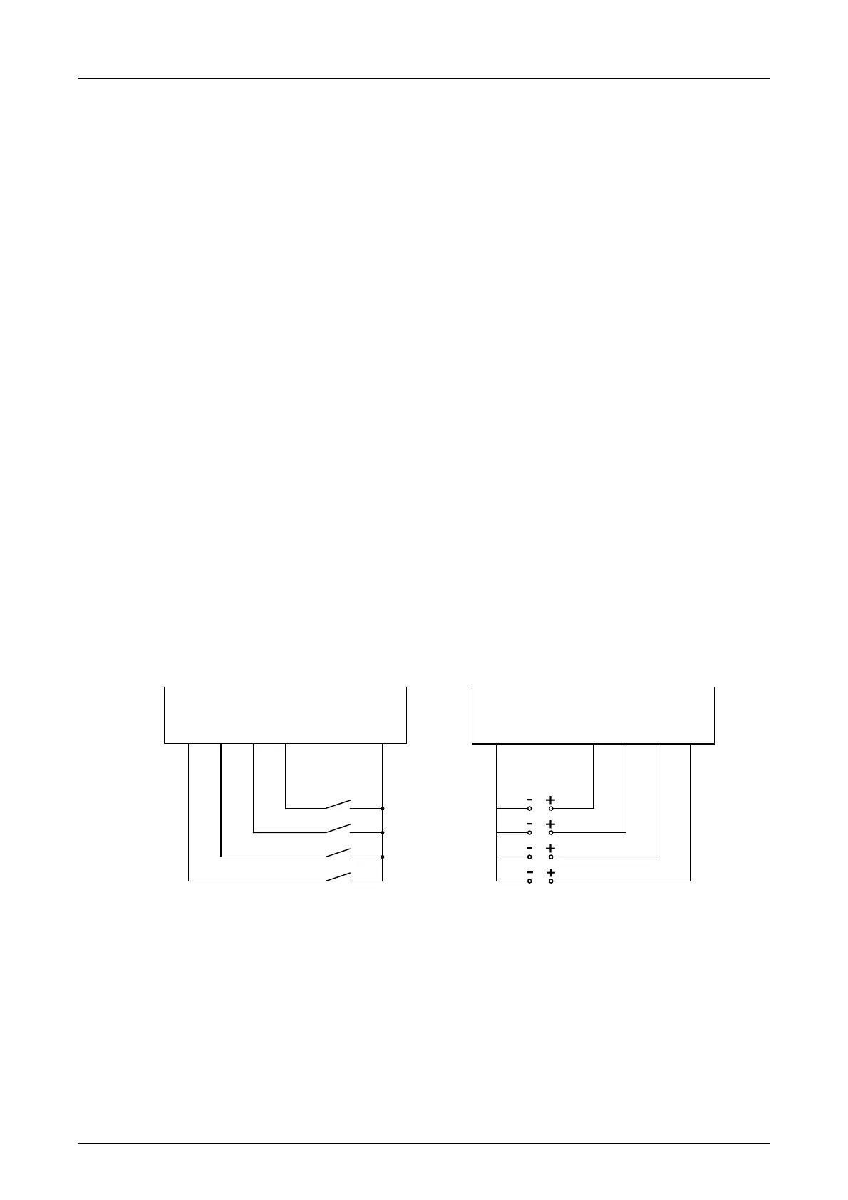
Mechanical contacts without own power supply or signal power source can be connected to the
inputs. Potential-free mechanical contacts without own power supply are fed via an internal
short-circuit-proof 24 V power source (LS+). Each of them supply a group of 4 mechanical
contacts. Figure 1 shows how the connection is performed.
With sig
nal voltage sources, the corresponding ground must be connected to the input (L-), see
Figure 1.
DI 1
LS+
DI 4
DI 3
DI 2
DI 1
L-
DI 4
DI 3
DI 2
Connection of potential-free mechanical
contacts
Connection of signal power sources
Figure 1: Connections to Safety-Related Digital Inputs
Table 18 shows the entire terminal assignment for the digital inputs.
In the default setting, ea
ch of the 24 V power sources (LS+) provides a current of 40 mA which
is buffered against power failures for 20 ms.
If higher current is required, the DI Supply[xx] system parameter can be set in the user program
to connect an unbuffered power source (1 A) for each terminal pair (33, 34 and 43, 44) and (53,
54 and 63, 64), see Figure 2 and Figure 3.