EasyManuals Logo
Home>HIMA>Computer Hardware>HIMax X-CPU 01

HIMA HIMax X-CPU 01 User Manual

HIMA HIMax X-CPU 01
52 pages
To Next Page IconTo Next Page
To Previous Page IconTo Previous Page
Page #12 background imageLoading...
Page #12 background image
3 Product Description X-CPU 01
Page 12 of 52 HI 801 009 E Rev. 4.00
3.4 Structure
The processor module is a plug-in module that is inserted into a base plate and supplied
with electric power.
Functional units of the module:
Safety-related processor system 1oo2
System controller
Ethernet switch
Memory
Mode switch, see Chapter
3.4.18.
Indicators, see Chapter
3.4.11.
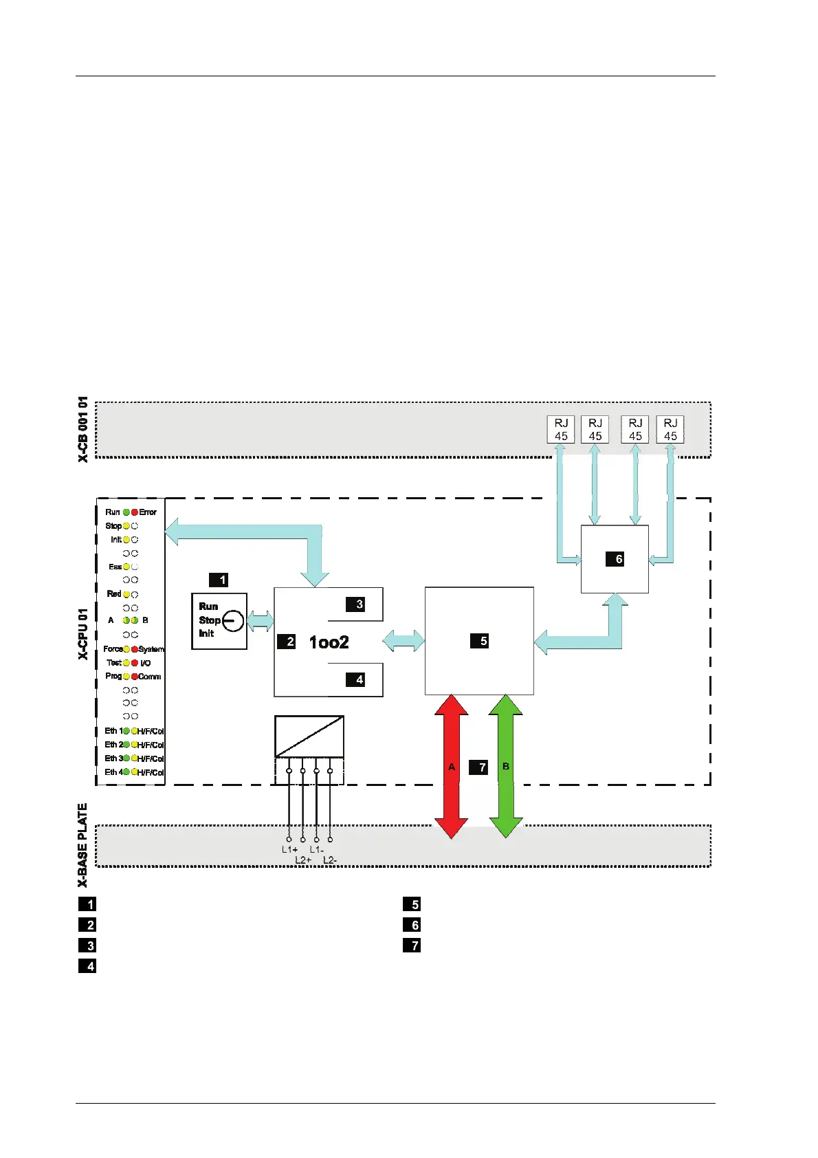
3.4.1 Block Diagram, Functional Units
The following block diagram illustrates the structure of the module.
Mode Switch
1oo2 Processor System
Comparator
Watchdog
System Controller
Ethernet Switch
System Bus A and System Bus B
Figure 2: Block Diagram

Table of Contents

Questions and Answers:

Question and Answer IconNeed help?

Do you have a question about the HIMA HIMax X-CPU 01 and is the answer not in the manual?

HIMA HIMax X-CPU 01 Specifications

General IconGeneral
BrandHIMA
ModelHIMax X-CPU 01
CategoryComputer Hardware
LanguageEnglish