3 Product Description X-CPU 01
Page 26 of 52 HI 801 009 E Rev. 4.00
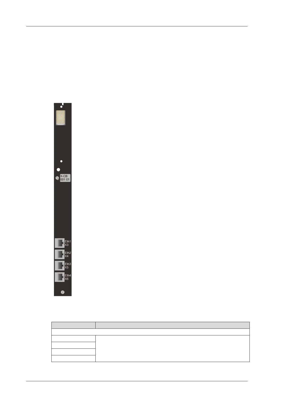
3.6 Connector Board
The X-CB 001 01 connector board connects the module with other HIMA controllers or with
the PADT. Module and connector board form together a functional unit. The connector
board contains the four ports (Eth1...Eth4) of the Ethernet switch on the processor module.
3.6.1 Connecting Options
Connection to other HIMA controllers.
Connection of the PADT
Figure 5: X-CB 001 01 Connector Board
Designation Description
Ethernet Interfaces
Eth1, X3
Eth2, X4
Eth3, X5
Eth4, X6
Connections for Ethernet:
Chapter
3.4.9 describes the characteristics of the external Ethernet
connections. The pin assignment of the RJ-45 connectors complies
with the applicable standards.
Table 16: Pin Assignment of X-CB 001 01