R
c
R
x
R
p
I
C.T.
1:n
Oscillator
Synchronous
rectifier
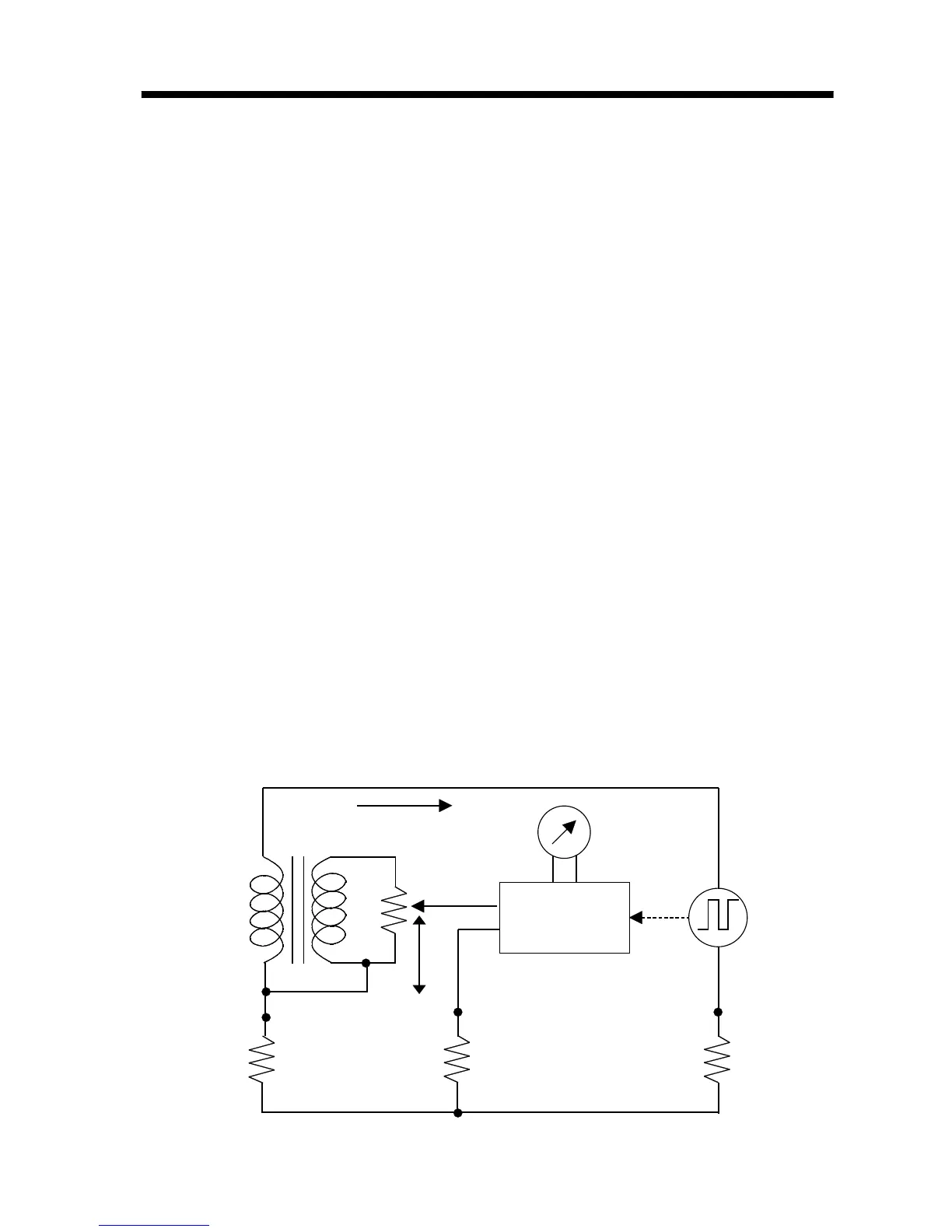
Figure 1 Measurement Principle (3-pole method)
3.2 Measurement Principle
(1) Normal measurement (3-pole method)
Figure 1 shows the basic circuit principle for
earthing resistance measurement. The
measuring current I, driven by the oscillating
voltage of the oscillator, flows through the loop
formed as follows: oscillator
→
Rc
→
Rx
→
C.T.
If the galvanometer is balanced, the voltage
between the measurement terminals
E-P(S)is
taken as Ex, and the resistance between the
measurement terminal
E and the slider S of the
variable resistor is taken as Rs. The voltage
drop at the variable resistor is Es.
The following equations then apply:
Ex =
IR
x, Es =
IR
s/n (n: C.T. winding ratio)
Ex = Es, therefore
R
x=
R
s/n
If the dial connected directly to the sliding
resistor has a scale of 1/n for Rs, the dial reading
corresponds to the earthing resistance Rx.