17
―――――――――――――――――――――――――――
Chapter 4 Measurement Procedure
――――――――――――――――――――――――
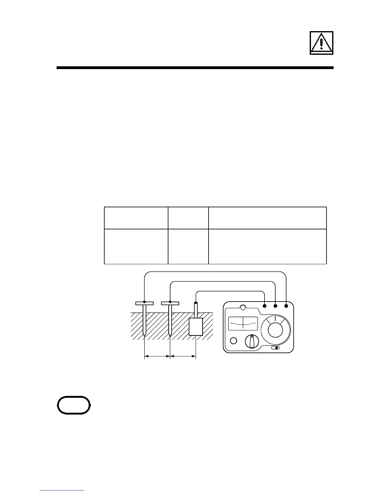
Measuremen
tterminal
Lead Object to be connected
E black Measurement object E
P (S) yellow Auxiliary earthing rods P
C (H) red Auxiliary earthing rods C
Figure 3 Normal Measurement Connection
CP E E
R
x
5-10 m
5-10 m
PC
NOTE
4.2 Normal Measurement (3-Pole
Method)
(1) Connections
Connect the measurement terminals to the
measurement object using the supplied
measurement leads, as shown in Figure 3.
Drive the auxiliary earthing rods
P and C deep
into the ground, at intervals of 5 - 10 meters
(straight line) from the measurement object E.
The ground into which the auxiliary earthing
rods are driven should be as humid as
possible. If the rods cannot be driven into the
ground, such as on concrete surfaces, use the
9050 EARTH NETS available as an option.
(See Section 4.4)