Do you have a question about the Hioki CM4001 and is the answer not in the manual?
Manual contents are subject to change; latest edition available on Hioki's website.
Register your product for important information.
Steps to turn on, clamp the instrument, and read the measured value.
Watch a YouTube video highlighting the meter's ease of use and speed.
Guidance on measuring leakage current in single-phase, three-phase, and other circuits.
How to identify insulation failures and GFCI/RCD trip events using leakage current.
Precautions and guidelines for measuring load current accurately.
Instructions for manually freezing the displayed measurement value.
How the instrument automatically freezes the display when values stabilize.
Display indicators and warnings during active event logging.
Procedure to stop and reset the event logging function.
How to use and control the display backlight for visibility.
Explanation of the warning backlight for overload, overrange, and function alerts.
Guide to using GENNECT Cross for data management and reporting.
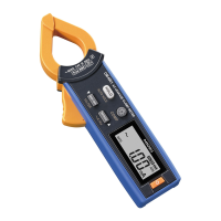
The HIOKI CM4001 is an AC Leakage Clamp Meter designed for measuring AC leakage current and other related electrical parameters. This instruction manual provides comprehensive guidance on its operation, features, and maintenance, ensuring users can effectively utilize the device for various electrical measurement tasks.
The primary function of the CM4001 is to measure AC leakage current, which is crucial for identifying insulation failures and ensuring electrical safety. It also offers capabilities for measuring load current, inrush current, and frequency. The device is equipped with a filter function to eliminate unnecessary high-frequency components, allowing for more accurate measurements in complex electrical environments.
The CM4001 facilitates leakage current measurement in both single-phase 3-wire and 3-phase 3-wire circuits. For single-phase 3-wire circuits, the instrument can be clamped around two wires bundled together. In 3-phase 3-wire circuits, it can be clamped around three wires bundled together. For 3-phase 4-wire circuits, all four wires should be bundled. The measurement principle involves detecting the imbalance in current flowing through the bundled wires, which indicates leakage current to the ground. The manual emphasizes the importance of clamping all relevant wires in a bundle to ensure accurate readings and avoid errors. It also warns against clamping around individual wires for leakage current measurement, as this will not yield correct results.
A key application of the CM4001 is to locate insulation failures that can cause ground-fault circuit interrupter (GFCI) or residual-current device (RCD) trip events. By measuring the leakage current of the entire circuit at the transformer's ground wire, users can determine the presence of an earth leakage. Once an earth leakage is detected, the instrument can be used to perform bundled measurements of all wires from the power supply side toward the load side to pinpoint the exact location of the insulation failure. The manual illustrates this process with diagrams for single-phase 3-wire circuits, showing how to identify insulation deterioration at different points in the circuit.
While primarily a leakage clamp meter, the CM4001 can also measure load current. For accurate load current measurement, the instrument must be clamped around only one conductor wire. It cannot measure load current when clamped around two or more wires bundled together. The conductor should be placed perpendicular to the sensor for optimal readings. The device may not accurately measure rush current or significantly fluctuating currents. The manual also notes that the instrument might display a non-zero readout without input at low temperatures, but this does not affect actual measurements.
The CM4001 can measure AC inrush current, which is the maximum instantaneous input current drawn by an electrical device when it is first turned on. This feature is enabled by simultaneously holding down the MAX/MIN and RANGE keys for 1 second or more. The inrush measurement range is automatically set based on the current measurement range. This function is useful for troubleshooting issues related to circuit breakers tripping upon equipment startup.
The CM4001 incorporates several features to enhance usability and measurement efficiency.
To perform a measurement, the user first turns on the instrument. The default setting is AUTO range. The range can be switched as required using the RANGE key, cycling through 60.00 mA, 600.0 mA, 6.000 A, 60.00 A, and 600.0 A. After setting the range, the instrument is clamped around the object under measurement. It is recommended to wear appropriate protective gear, such as gloves, during this process. The instrument should be clamped so that the object under measurement is located at the center of the jaws for the most accurate reading.
The filter function is designed to eliminate unnecessary high-frequency components that may be superimposed on the leakage current waveform, especially when measuring objects connected to switching power supplies or inverters. To enable or disable the filter, the MAX/MIN key is held down for 1 second or more. The manual warns that if the filter function is enabled and measured values vary greatly depending on the range selected manually, users should trust the measurement using the upper range.
The CM4001 offers both manual and auto-hold functions.
HOLD symbol appears on the display when activated.This feature allows the instrument to display the maximum, minimum, average, highest peak, or lowest peak values of the measured data. The auto power save function is disabled when using this mode. To activate, the user clamps the instrument, sets the range, and then presses the MAX/MIN key. Each press cycles through MAX, MIN, AVG, PEAK MAX, and PEAK MIN. Holding down the MAX/MIN key for 1 second or more cancels this function. The manual clarifies that AVG refers to the average RMS value of all measured values.
The comparator function alerts the user when a measured value exceeds a preset threshold. When activated, a buzzer sounds, and the warning backlight lights up in red. This function is enabled by holding down the COMP key for 1 second or more. The threshold value can be set using the MAX/MIN or RANGE keys. Once confirmed by pressing the HOLD key, the instrument returns to the measurement screen. The auto range cannot be used when the comparator function is enabled.
This function allows the instrument to record maximum values from the start to the stop of recording. If the maximum value exceeds a set threshold, the backlight flashes red as a warning. To enable, turn on the instrument while holding down the HOLD and COMP keys simultaneously. The threshold value can be selected using the MAX/MIN or RANGE keys and confirmed with the HOLD key. The filter function can also be enabled or disabled in this mode. Once logging starts, the instrument displays the maximum value from the recording start, and the blinking red backlight indicates an exceedance of the threshold. To stop logging, press MAX/MIN or RANGE, then HOLD.
With the optional Z3210 Wireless Adapter installed, the CM4001 can communicate wirelessly with mobile devices via GENNECT Cross application. This allows users to check and record measured data, create measurement reports, and perform other advanced functions like event logging, waveform graphs, harmonic analysis, and firmware updates.
The CM4001 includes an auto power save function to conserve battery life. It is enabled automatically when the instrument is turned on. For continuous use over extended periods, the APS function can be disabled by turning on the instrument while holding down the HOLD key.
The display backlight ensures clear visibility in dark environments. Pressing the backlight key turns it on or off. It automatically turns off after approximately 40 seconds of inactivity. To disable the automatic backlight shutoff, turn on the instrument while holding down the backlight key.
The warning backlight serves as a critical safety feature, illuminating or blinking red under specific conditions:
It is important to note that the warning backlight only works for the present measured value and not for frozen or recorded values in MAX, MIN, AVG, PEAK MAX, and PEAK MIN display functions.
| Type | Clamp Meter |
|---|---|
| Measuring Range AC Voltage | 0.1 V to 600 V |
| Measuring Range DC Voltage | 0.1 V to 600 V |
| Display | Digital LCD |
| Continuity | 50 Ω ±40 Ω |
| Operating Temperature | -25 °C to 65 °C |
| Display Digits | 6000 counts |
| Crest Factor | 2.5 |
| Power Supply | AA battery × 2 |
| Measurement Category | CAT III 600 V |
| Basic Accuracy (AC/DC voltage) | ±1.0% ±3 digits |
| Display Counts | 6000 |
| Power Supply Option | AA alkaline battery (LR6) x2 |
| Safety Standards | EN 61010 |
| Frequency Measurement | 10.0 Hz to 1.000 kHz |
| AC Current Accuracy | ±1.5% ±5 digits |
| Frequency | 10.0 Hz to 1.000 kHz |
| Basic Accuracy (AC/DC current) | ±1.5% ±5 digits |